Injection molding
From Wikipedia, the free encyclopedia
|
|
It has been suggested that Injection molding machine be merged into this article or section. (Discuss) |
Injection molding (British English: moulding) is a manufacturing process for producing parts from both thermoplastic and thermosetting plastic materials. Material is fed into a heated barrel, mixed, and forced into a mold cavity where it cools and hardens to the configuration of the mold cavity. [1] After a product is designed, usually by an industrial designer or an engineer, molds are made by a moldmaker (or toolmaker) from metal, usually either steel or aluminium, and precision-machined to form the features of the desired part. Injection molding is widely used for manufacturing a variety of parts, from the smallest component to entire body panels of cars.

[edit] Process Characteristics
- Utilizes a ram or screw-type plunger to force molten plastic material into a mold cavity
- Produces a solid or open-ended shape which has conformed to the contour of the mold
- Uses thermoplastic or thermoset materials
- Produces a parting line, sprue, and gate marks
- Ejector pin marks are usually present
[edit] History
In 1868 John Wesley Hyatt developed a plastic material he named Celluloid which had been invented in 1851 by Alexander Parks. Hyatt improved it so that it could be processed into finished form. In 1872 John, with his brother Isaiah, patented the first injection molding machine.[3] This machine was relatively simple compared to the machines we use today. It basically worked like a large hypodermic needle injecting plastic through a heated cylinder into a mold. The industry progressed slowly over the years producing products such as collar stays, buttons, and hair combs until it exploded in the 1940s because World War 2 created a huge demand for inexpensive, mass-produced products. In 1946 James Hendry built the first screw injection machine. This machine allowed material to be mixed before injection, which meant colored plastic or recycled plastic could be added to the virgin material and mixed thoroughly before being injected. Today screw injection machines account for 95% of all injection machines. The industry has evolved over the years from producing combs and buttons to producing a vast array of products for many industries including automotive, medical, aerospace, consumer, toys, plumbing, packaging, and construction.[4]
[edit] Applications
Injection molding is used to create many things such as milk cartons, containers, bottle caps, automotive dashboards, pocket combs, and most other plastic products available today. Injection molding is the most common method of part manufacturing. It is ideal for producing high volumes of the same object.[5] Some advantages of injection molding are high production rates, high tolerances are repeatable, wide range of materials can be used, low labour cost, minimal scrap losses, and little need to finish parts after molding. Some disadvantages of this process are expensive equipment investment, running costs may be high, and parts must be designed with molding consideration.[6]
[edit] Examples of Polymers Best Suited for the Process
Most polymers may be used, including all thermoplastics, some thermosets, and some elastomers.[7] In 1995 there were approximately 18,000 different materials available for injection molding and that number was increasing at an average rate of 750 per year. The available materials are alloys or blends of previously developed materials meaning that product designers can choose from a vast selection of materials, one that has exactly the right properties. Materials are chosen based on the strength and function required for the final part but also each material has different parrameters for molding that must be taken into account.[8] Common polymers like Epoxy and phenolic are examples of thermosetting plastics while nylon, polyethylene, and polystyrene are thermoplastic.[9]
[edit] Design Considerations for the Process
It is important when designing products for injection molding that you consider how they will be formed in the machine, how they will be taken out of the machine, and the structure of the final product. Some important guidelines are:
1. Use approximately uniform wall thicknesses throughout your designs.
2. Keep walls thin - typically between 1/32" and 1/10". This allows for proper cooling and reduces cost by minimizing use of material. Thin walls also reduce problems with material shrinkage. Although some unevenness will occur due to shrinkage, walls as thick as 1/5" can be used. Keep wall thickness at least wall length / 50. Keep 90 deg walls under 0.25" high. Keep thickness of ejection pin surface wall at least .07".
3. To strengthen parts, instead of using thicker walls, use additional structures such as ribs. Use fillets at the base of ribs.
4. When using a rib make it about half the main wall thickness.
5. Round corners and edges wherever possible.
6. For easy release of the part from the mold, add a slight taper to the sides (typically ~ 2 deg) - especially for textured walls and walls higher than 0.25".
7. Avoid undercuts that are impossible to remove from the mold.
8. Lighter colors hide flow patterns better than dark colors.
9. Where walls meet at a 90 angle, round inside and outside to at least .05" radius - sharper outside corners can create molding problems and sharper inside corners will increase tooling cost.
10. Keep holes at least .015" from edges.[10]
[edit] Equipment

Injection molding machines consist of a material hopper, an injection ram or screw-type plunger, and a heating unit.[11] They are also known as presses, they hold the molds in which the components are shaped. Presses are rated by tonnage, which expresses the amount of clamping force that the machine can exert. This force keeps the mold closed during the injection process. Tonnage can vary from less than 5 tons to 6000 tons, with the higher figures used in comparatively few manufacturing operations. The total clamp force needed is determined by the projected area of the part being molded. This projected area is multiplied by a clamp force of from 2 to 8 tons for each square inch of the projected areas. As a rule of thumb, 4 or 5 tons/in2 can be used for most products. If the plastic material is very stiff, it will require more injection pressure to fill the mold, thus more clamp tonnage to hold the mold closed.[12] The required force can also be determined by the material used and the size of the part, larger parts require higher clamping force.[13]
[edit] Mold
Mold or die are the common terms used to describe the tooling used to produce plastic parts in molding.
Traditionally, molds have been expensive to manufacture. They were usually only used in mass production where thousands of parts were being produced. Molds are typically constructed from hardened steel, pre-hardened steel, aluminium, and/or beryllium-copper alloy. The choice of material to build a mold from is primarily one of economics, steel molds generally cost more to construct, but their longer lifespan will offset the higher initial cost over a higher number of parts made before wearing out. Pre-hardened steel molds are less wear resistant and are used for lower volume requirements or larger components. The steel hardness is typically 38-45 on the Rockwell-C scale. Hardened steel molds are heat treated after machining. These are by far the superior in terms of wear resistance and lifespan. Typical hardness ranges between 50 and 60 Rockwell-C (HRC). Aluminium molds can cost substantially less, and when designed and machined with modern computerized equipment, can be economical for molding tens or even hundreds of thousands of parts. Beryllium copper is used in areas of the mold which require fast heat removal or areas that see the most shear heat generated.[14] The molds can be manufactured by either CNC machining or by using Electrical Discharge Machining processes
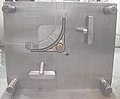 "A" side of die for 25% glass-filled acetal with 2 side pulls. |
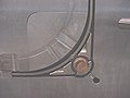 Close up of removable insert in "A" side. |
 "B" side of die with side pull actuators. |
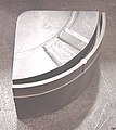 Insert removed from die. |
[edit] Mold Design

The mold consists of two primary components, the injection mold (A plate) and the ejector mold (B plate). Plastic resin enters the mold through a sprue in the injection mold, the sprue bushing is to seal tightly against the nozzle of the injection barrel of the molding machine and to allow molten plastic to flow from the barrel into the mold, also known as cavity[15] The sprue bushing directs the molten plastic to the cavity images through channels that are machined into the faces of the A and B plates. These channels allow plastic to run along them, so they are referred to as runners.[16] The molten plastic flows through the runner and enters one or more specialized gates and into the cavity[17] geometry to form the desired part.
The amount of resin required to fill the sprue, runner and cavities of a mold is a shot. Trapped air in the mold can escaped through air vents that are grinded into the parting line of the mold. If the trapped air is not allowed to escape, it is compressed by the pressure of the incoming material and is squeezed into the corners of the cavity, where it prevents filling and causes other defects as well. The air can become so compressed that it ignites and burns the surrounding plastic material.[18] To allow for removal of the molded part from the mold, the mold features must not overhang one another in the direction that the mold opens, unless parts of the mold are designed to move from between such overhangs when the mold opens (utilizing components called Lifters).
Sides of the part that appear parallel with the direction of draw (The axis of the cored position (hole) or insert is parallel to the up and down movement of the mold as it opens and closes)[19] are typically angled slightly with (draft) to ease release of the part from the mold. Insufficient draft can cause deformation or damage. The draft required for mold release is primarily dependent on the depth of the cavity: the deeper the cavity, the more draft necessary. Shrinkage must also be taken into account when determining the draft required.[20] If the skin is too thin, then the molded part will tend to shrink onto the cores that form them while cooling, and cling to those cores or part may warp, twist, blister or crack when the cavity is pulled away.[21] The mold is usually designed so that the molded part reliably remains on the ejector (B) side of the mold when it opens, and draws the runner and the sprue out of the (A) side along with the parts. The part then falls freely when ejected from the (B) side. Tunnel gates, also known as submarine or mold gate, is located below the parting line or mold surface. The opening is machined into the surface of the mold on the parting line. The molded part is cut (by the mold) from the runner system on ejection from the mold.[22] Ejector pins, also known as knockout pin, is a circular pin placed in either half of the mold (usually the ejector half) which pushes the finished molded product, or runner system out of a mold.[23]
The standard method of cooling is passing a coolant (usually water) through a series of holes drilled through the mold plates and connected by hoses to form a continueous pathway. The coolant absorbs heat from the mold (which has absorbed heat from the hot plastic) and keeps the mold at a proper temperature to solidify the plastic at the most efficient rate.[24]
To ease maintenance and venting, cavities and cores are divided into pieces, called inserts, and sub-assemblies, also called inserts, blocks, or chase blocks. By substituting interchangeable inserts, one mold may make several variations of the same part.
More complex parts are formed using more complex molds. These may have sections called slides, that move into a cavity perpendicular to the draw direction, to form overhanging part features. When the mold is opened, the slides are pulled away from the plastic part by using stationary “angle pins” on the stationary mold half. These pins enter a slot in the slides and cause the slides to move backward when the moving half of the mold opens. The part is then ejected and the mold closes. The closing action of the mold causes the slides to move forward along the angle pins.[25]
Some molds allow previously molded parts to be reinserted to allow a new plastic layer to form around the first part. This is often referred to as overmolding. This system can allow for production of one-piece tires and wheels.
2-shot or multi-shot molds are designed to "overmold" within a single molding cycle and must be processed on specialized injection molding machines with two or more injection units. This process is actually an injection molding process performed twice. In the first step, the base color material is molded into a basic shape. Then the second material is injection-molded into the remaining open spaces. That space is then filled during the second injection step with a material of a different color.[26]
A mold can produce several copies of the same parts in a single "shot". The number of "impressions" in the mold of that part is often incorrectly referred to as cavitation. A tool with one impression will often be called a single impression(cavity) mold.[27] A mold with 2 or more cavities of the same parts will likely be referred to as multiple impression (cavity) mold.[28] Some extremely high production volume molds (like those for bottle caps) can have over 128 cavities.
In some cases multiple cavity tooling will mold a series of different parts in the same tool. Some toolmakers call these molds family molds as all the parts.[29]
[edit] Effects on the material properties
The mechanical properties of a part are usually little effected. Some parts can have internal stresses in them. This is one of the reasons why it's good to have uniform wall thickness when molding. One of the physical property changes is shrinkage. A permanent chemical property change is the material thermoset, which can't be remelted to be injected again.[30]
[edit] Tool Materials
Tool steel or beryllium-copper are often used. Mild steel, aluminum, nickel or epoxy are only suitable for prototype or very short production runs. [31]
[edit] Geometrical Possibilities
The most commonly used plastic molding process, injection molding, is used to create a large variety of products with different shapes and sizes. Most importantly, they can create products with complex geometry that many other processes cannot. There are a few precautions when designing something that will be made using this process to reduce the risk of weak spots. First, streamline your product or keep the thickness relatively uniform. Second, try and keep your product between 2 to 20 inches.
The size of a part will depend on a number of factors (material, wall thickness, shape,process ect). The initial raw material required may be measured in the form of granules, pellets or powders. Here are some ranges of the sizes.
| Method | Raw Materials | Maximum Size | Minimum Size |
|---|---|---|---|
| Injection Molding (thermo-plastic) | Granules, Pellets, Powders | 700 oz. | Less than 1 oz. |
| Injection Molding (thermo-setting) | Granules, Pellets, Powders | 200 oz. | Less Than 1 oz. |
[edit] Machining
Molds are built through two main methods: standard machining and EDM. Standard Machining, in its conventional form, has historically been the method of building injection molds. With technological development, CNC machining became the predominant means of making more complex molds with more accurate mold details in less time than traditional methods.
The electrical discharge machining (EDM) or spark erosion process has become widely used in mold making. As well as allowing the formation of shapes which are difficult to machine, the process allows pre-hardened molds to be shaped so that no heat treatment is required. Changes to a hardened mold by conventional drilling and milling normally require annealing to soften the steel, followed by heat treatment to harden it again. EDM is a simple process in which a shaped electrode, usually made of copper or graphite, is very slowly lowered onto the mold surface (over a period of many hours), which is immersed in paraffin oil. A voltage applied between tool and mold causes spark erosion of the mold surface in the inverse shape of the electrode.[33]
[edit] Cost
The cost of manufacturing molds depends on a very large set of factors ranging from number of cavities, size of the parts (and therefore the mold), complexity of the pieces, expected tool longevity, surface finishes and many others. The initial cost is great, however the piece part cost is low, so with greater quantities the overall price decreases.
[edit] Injection process

With Injection Molding, granular plastic is fed by gravity from a hopper into a heated barrel. As the granules are slowly moved forward by a screw-type plunger, the plastic is forced into a heated chamber, where it is melted. As the plunger advances, the melted plastic is forced through a nozzle that rests against the mold, allowing it to enter the mold cavity through a gate and runner system. The mold remains cold so the plastic solidifies almost as soon as the mold is filled.[34]
[edit] Injection Molding Cycle
The sequence of events during the injection mold of a plastic part is called the injection molding cycle. The cycle begins when the mold closes, followed by the injection of the polymer into the mold cavity. Once the cavity is filled, a holding pressure is maintained to compensate for material shrinkage. In the next step, the screw turns, feeding the next shot to the front screw.This causes the screw to retract as the next shot is prepared. Once the part is sufficiently cool, the mold opens and the part is ejected. [35]
[edit] Time Function
|
The time it takes to make a product using injection molding can be calculated by adding: |
The total cycle time can be calculated using tcycle = tclosing + tcooling + tejection[37]
- The closing and ejection times, can last from a fraction of a second to a few seconds, depending on the size of the mold and machine. The cooling times, which dominate the process, depend on the maximum thickness of the part.[38]
[edit] Different types of Injection Molding Processes
Although most injection molding processes are covered by the conventional process description above, there are several important molding variations including:
- Co-injection(sandwich)molding
- Fusible(lost, soluble)core injection molding
- Gas-assisted injection molding
- In-mold decoration and in mold lamination
- Injection-compression molding
- Insert and outsert molding
- Lamellar (microlayer) injection molding
- Low-pressure injection molding
- Microinjection molding
- Microcellular molding
- Multicomponent injection molding(overmolding)
- Multiple live-feed injection molding
- Powder injection molding
- Push-Pull injection molding
- Reaction injection molding
- Resin transfer molding
- Rheomolding
- Structural foam injection molding
- Structural reaction injection molding
- Thin-wall molding
- Vibration gas injection molding
- Water assisted injection molding
- Rubber injection
- Injection molding of liquid silicone rubber[39]
For more details about the different types injection processes.[1]
[edit] Process Troubleshooting
Optimal process settings are critical to influencing the cost, quality, and productivity of plastic injection molding. Process optimization is done using the following methods. Injection speeds are usually determined by performing viscosity curves. Process windows are performed varying the melt temperatures and holding pressures. Pressure drop studies are done to check if the machine has enough pressure to move the screw at the set rate. Gate seal or gate freeze studies are done to optimize the holding time. A cooling time study is done to optimize the cooling time.
[edit] Molding trial
When filling a new or unfamiliar mold for the first time, where shot size for that mold is unknown, a technician/tool setter usually starts with a small shot weight and fills gradually until the mold is 95 to 99% full. Once this is achieved a small amount of holding pressure will be applied and holding time increased until gate freeze off (solidification time) has occurred. Gate solidification time is an important as it determines cycle time, which itself is an important issue in the economics of the production process.[40] Holding pressure is increased until the parts are free of sinks and part weight has been achieved. Once the parts are good enough and have passed any specific criteria, a setting sheet is produced for people to follow in the future.
[edit] Molding defects
Injection molding is a complex technology with possible production problems. They can either be caused by defects in the molds or more often by part processing (molding)
| Molding Defects | Alternative name | Descriptions | Causes |
|---|---|---|---|
| Blister | Blistering | Raised or layered zone on surface of the part | Tool or material is too hot, often caused by a lack of cooling around the tool or a faulty heater |
| Burn marks | Air Burn/ Gas Burn | Black or brown burnt areas on the part located at furthest points from gate | Tool lacks venting, injection speed is too high |
| Color streaks (US) | Colour streaks (UK) | Localized change of color/colour | Masterbatch isn't mixing properly, or the material has run out and it's starting to come through as natural only |
| Delamination | Thin mica like layers formed in part wall | Contamination of the material e.g. PP mixed with ABS, very dangerous if the part is being used for a safety critical application as the material has very little strength when delaminated as the materials cannot bond | |
| Flash | Burrs | Excess material in thin layer exceeding normal part geometry | Tool damage, too much injection speed/material injected, clamping force too low. Can also be caused by dirt and contaminants around tooling surfaces. |
| Embedded contaminates | Embedded particulates | Foreign particle (burnt material or other) embedded in the part | Particles on the tool surface, contaminated material or foreign debris in the barrel, or too much shear heat burning the material prior to injection |
| Flow marks | Flow lines | Directionally "off tone" wavy lines or patterns | Injection speeds too slow (the plastic has cooled down too much during injection, injection speeds must be set as fast as you can get away with at all times) |
| Jetting | Deformed part by turbulent flow of material | Poor tool design, gate position or runner. Injection speed set too high. | |
| Polymer degradation | polymer breakdown from hydrolysis, oxidation etc | Excess water in the granules, excessive temperatures in barrel | |
| Sink marks | Localized depression (In thicker zones) | Holding time/pressure too low, cooling time too short, with sprueless hot runners this can also be caused by the gate temperature being set too high | |
| Short shot | Non-fill / Short mold | Partial part | Lack of material, injection speed or pressure too low |
| Splay marks | Splash mark / Silver streaks | Circular pattern around gate caused by hot gas | Moisture in the material, usually when hygroscopic resins are dried improperly |
| Stringiness | Stringing | String like remain from previous shot transfer in new shot | Nozzle temperature too high. Gate hasn't frozen off |
| Voids | Empty space within part (Air pocket) | Lack of holding pressure (holding pressure is used to pack out the part during the holding time). Also mold may be out of registration (when the two halves don't center properly and part walls are not the same thickness). | |
| Weld line | Knit line / Meld line | Discolored line where two flow fronts meet | Mold/material temperatures set too low (the material is cold when they meet, so they don't bond) |
| Warping | Twisting | Distorted part | Cooling is too short, material is too hot, lack of cooling around the tool, incorrect water temperatures (the parts bow inwards towards the hot side of the tool) |
[edit] Tolerances and Surfaces
Molding tolerance is a specified allowance on the deviation in parameters such as dimensions, weights, shapes, or angles, ect. To maximize control in setting tolerances there is usually a minimum and maximum limit on thickness, based on the process used.[41] Injection molding typically is capable of tolerances equivalent to an IT Grade of about 9–14. The possible tolerance of a thermoplastic or a thermoset is ±0.008 to ±0.002 inches. Surface finishes of two to four microinches or better are can be obtained. Rough or pebbled surfaces are also possible.
| Molding Type | Typical | Possible |
|---|---|---|
| Thermoplastic | ±0.008 | ±0.002 |
| Thermoset | ±0.008 | ±0.002 |
[edit] Lubrication and Cooling
Obviously, the mold must be cooled in order for the production to take place. Because of the heat capacity, inexpensiveness, and availability of water, water is used as the primary cooling agent. To cool the mold, water can be channeled through the mold to account for quick cooling times. Usually a colder mold is more efficient because this allows for faster cycle times. However, this is not always true because crystalline materials require the opposite of a warmer mold and lengthier cycle time. [42]
[edit] Power Requirements
The power required for this process of injection molding depends on many things and varies between materials used. Manufacturing Processes Reference Guide states that the power requirements depend on "a material's specific gravity, melting point, thermal conductivity, part size, and molding rate." Below is a table from page 243 of the same reference as previously mentioned which best illustrates the characteristics relevant to the power required for the most commonly used materials.
| Material | Specific Gravity | Melting Point (°F) |
|---|---|---|
| Epoxy | 1.12 to 1.24 | 248 |
| Phenolic | 1.34 to 1.95 | 248 |
| Nylon | 1.01 to 1.15 | 381 to 509 |
| Polyethylene | 0.91 to 0.965 | 230 to 243 |
| Polystyrene | 1.04 to 1.07 | 338 |
[edit] Inserts
Metal inserts can be also be injection molded into the workpiece. For large volume parts the inserts are placed in the mold using automated machinery. An advantage of using automated components is that the smaller size of parts allows a mobile inspection system that can be used to examine multiple parts in a decreased amount of time. In addition to mounting inspection systems on automated components, multiple axial robots are also capable of removing parts from the mold and place them in latter systems that can be used to ensure quality of multiple parameters. The ability of automated components to decrease the cycle time of the processes allows for a greater output of quality parts.[43]
Specific instances of this increased efficiency include the removal of parts from the mold immediately after the parts are created and use in conjunction with vision systems. The removal of parts is achieved by using robots to grip the part once it has become free from the mold after in ejector pins have been raised. The robot then moves these parts into either a holding location or directly onto an inspection system, depending on the type of product and the general layout of the rest of the manufacturer's production facility. Visions systems mounted on robots are also an advancement that has greatly changed the way that quality control is performed in insert molded parts. A mobile robot is able to more precisely determine the accuracy of the metal component and inspect more locations in the same amount of time as a human inspector.[43]
[edit] See also
- Reaction injection molding, a similar technique to standard injection molding, enables the use of thermoset polymers to produce large and complex parts.
- Liquid injection molding, a process that involves an integrated system for proportioning, mixing, and dispensing dual-component liquid resin formulations and directly injecting the resultant mix into a mold which is clamped under pressure.
- Hobby injection molding
[edit] Notes
- ^ Manufacturing Processes Reference Guide pg 240
- ^ Manufacturing Processes Reference Guide pg. 240
- ^ U.S. patent #133229, dated 19 November 1872.
- ^ Douglas M. Bryce. Plastic Injection Molding: Manufacturing Process Fundamentals. SME, 1996. pg.1-2
- ^ http://www.yaskawa.com/site/Industries.nsf/applicationDoc/appinjmold.html, 02/27/09
- ^ http://www.what-is-injection-molding.com/Default.aspx?tabid=36, 02/27/09
- ^ http://www.custompartnet.com/wu/InjectionMolding, 02/27/09.
- ^ Douglas M. Bryce. Plastic Injection Molding: Manufacturing Process Fundamentals. SME, 1996. pg.6
- ^ Manufacturing Processes Reference Guide pg. 242
- ^ http://www.emachineshop.com/machine-shop/Plastic-Injection-Molding-Design-Considerations/page391.html, 02/27/09
- ^ Manufacturing Processes Reference Guide pg. 240
- ^ Douglas M. Bryce. Plastic Injection Molding: Manufacturing Process Fundamentals. SME, 1996. pg.43-44
- ^ http://www.custompartnet.com/wu/InjectionMolding
- ^ Donald V. Rosato, Marlene G. Rosato. Concise Encyclopedia of Plastics. Springer, 2000. pg.176
- ^ Douglas M. Bryce. Plastic Injection Molding: Manufacturing Process Fundamentals. SME, 1996. pg.141
- ^ Douglas M. Bryce. Plastic Injection Molding: Manufacturing Process Fundamentals. SME, 1996. pg.142
- ^ Rosato Dominick , Rosato Marlene, and Rosato Donald Injection Molding Handbook 3rd Ed. Kluwer Academic Publishers, 2000. pg.15
- ^ Douglas M. Bryce. Plastic Injection Molding: Manufacturing Process Fundamentals. SME, 1996. pg.147
- ^ Rosato Dominick , Rosato Marlene, and Rosato Donald Injection Molding Handbook 3rd Ed. Kluwer Academic Publishers, 2000. pg.406
- ^ Rosato Dominick , Rosato Marlene, and Rosato Donald Injection Molding Handbook 3rd Ed. Kluwer Academic Publishers, 2000. pg.332
- ^ Douglas M. Bryce. Plastic Injection Molding: Manufacturing Process Fundamentals. SME, 1996. pg.47
- ^ Rosato Dominick , Rosato Marlene, and Rosato Donald Injection Molding Handbook 3rd Ed. Kluwer Academic Publishers, 2000. pg.288
- ^ Douglas M. Bryce. Plastic Injection Molding: Manufacturing Process Fundamentals. SME, 1996. pg.143
- ^ Douglas M. Bryce. Plastic Injection Molding: Manufacturing Process Fundamentals. SME, 1996. pg.86
- ^ Douglas M. Bryce. Plastic Injection Molding: Manufacturing Process Fundamentals. SME, 1996. pg.268
- ^ Douglas M. Bryce. Plastic Injection Molding: Manufacturing Process Fundamentals. SME, 1996. pg.174
- ^ Tony Whelan. Polymer Technology Dictionary Springer, 1994. pg.398
- ^ Tony Whelan. Polymer Technology Dictionary Springer, 1994. pg.262
- ^ Rees, Herbert; Catoen, Selecting Injection Molds - Weighing Cost versus Productivity Hanser Publishers, 2006. pg.114
- ^ Robert H. Todd, Dell K. Allen, Leo Alting. Manufacturing Processes Reference Guide Industrial Press Inc., 1994. pg. 243
- ^ Todd, R. H., Allen, D. K., & Alting, L. (1994). Manufacturing Processes Reference Guide. New York, NY: Industrial Press Inc.
- ^ Todd, R. H., Allen, D. K., & Alting, L. (1994). Manufacturing Processes Reference Guide. New York, NY: Industrial Press Inc.
- ^ http://advantagetool.us/mats/die_casting/
- ^ Manufacturing Processes Reference Guide
- ^ Injection Molding Handbook 2nd Ed pg 13
- ^ Manufacturing Processes Reference Guide
- ^ International Plastics Handbook
- ^ International Plastics Handbook
- ^ Injection Molding Handbook 2nd Ed pg 17-18
- ^ R Pantani, F De Santis, V Brucato, G Titomanlio Analysis of Gate Freeze-Off Time in Injection Molding. Polymer Engineering and Science, 2004
- ^ Rosato 2000, p. 439.
- ^ Manufacturing Processes Reference Guide
- ^ a b Callister.
[edit] References
- Bryce, Douglas M. Plastic Injection Molding: Manufacturing Process Fundamentals. SME, 1996.
- Brydson, J, Plastics Materials, Butterworths 9th Ed (1999).
- Callister, William D, Materials Science and Engineering: An Introduction, John Wiley and Sons
- Lewis, Peter Rhys, Reynolds, K, Gagg, C, Forensic Materials Engineering: Case studies, CRC Press (2004).
- Osswald, Tim A; Lih-Sheng Turng, Paul J.Gramamn. Injection Molding Handbook 2nd Ed. Hanser Verlag., 2007
- Osswald, Tim A. International Plastics Handbook. Hanser Verlag., 2006
- Rosato, Donald V; Marlene G. Rosato. Concise Encyclopedia of Plastics. Springer, 2000.
- Rosato, Dominick; Rosato Marlene, and Rosato Donald Injection Molding Handbook 3rd Ed. Kluwer Academic Publishers, 2000.
- Todd, Robert H; Dell K. Allen and Leo Alting Manufacturing Processes Reference Guide. Industrial Press Inc., 1994. pgs. 240-245
- Whelan, Tony. Polymer Technology Dictionary Springer, 1994.
[edit] External links
- Injection molding cost estimator
- Injection molding cost estimator (detailed)
- Injection molding machine states
- Shrinkage & warpage
- Injection molding guidelines

