Stirling engine
From Wikipedia, the free encyclopedia
|
|
This article or section has multiple issues. Please help improve the article or discuss these issues on the talk page.
|
|
|
This article includes a list of references or external links, but its sources remain unclear because it has insufficient inline citations. Please help to improve this article by introducing more precise citations where appropriate. (January 2009) |
A Stirling engine is a device that converts heat energy into mechanical power by alternately compressing and expanding a fixed quantity of air or other gas (the working fluid) at different temperatures.[1]
Originally conceived in 1816 as a rival to the steam engine as an industrial prime mover, practical use of the Stirling engine was largely confined to low-power domestic applications for over a century.[2] In recent years, the advantages of Stirling engines have become increasingly significant, given the rise in liquid fuel prices and concerns such as peak oil and climate change. Stirling engines address these issues by being very compatible with all renewable energy and fuel sources. The Stirling engine is noted for its high efficiency, quiet operation and the ease with which it can utilise what would otherwise be wasted heat and is currently exciting interest as the core component of Micro combined heat and power (CHP) units, widespread adoption of which could have a significant effect upon worldwide energy utilisation.[3][4]
Contents |
[edit] Name, formal definition and classification

Though it had been suggested as early as 1884 by Fleeming Jenkin that all closed cycle air engines should be generically called Stirling engines after Robert Stirling, the inventor of the first practical example, the idea found little favour and the various types on the market continued to be known by the name of their individual designer or manufacturer, e.g. Rider's, Robinson's or Heinrici's (hot) air engine. Then, in the 1940s, the Philips company was searching for a suitable name for its own version of the 'air engine', which by that time had already been tested with other gases, eventually settling on 'Stirling engine' in April 1945.[5] However, nearly thirty years later Graham Walker was still bemoaning the fact that such terms as 'hot air engine' continued to be used interchangeably with 'Stirling engine' which itself was applied widely and indiscriminately.[6] The situation has now improved somewhat, at least in academic literature, and it is now generally accepted that 'Stirling engine' should refer exclusively to a closed-cycle regenerative heat engine with a permanently gaseous working fluid, where closed-cycle is defined as a thermodynamic system in which the working fluid is permanently contained within the system and regenerative describes the use of a specific type of internal heat exchanger and thermal store, known as "the regenerator".
It follows from the closed cycle operation that the Stirling engine is an external combustion engine that isolates its working fluid from the energy input supplied by an external heat source.There are many possible implementations of the Stirling engine most of which fall into the category of reciprocating piston engine.
[edit] Functional description
The engine is designed so that the working gas is generally compressed in the colder portion of the engine and expanded in the hotter portion resulting in a net conversion of heat into work.[7][8] An internal Regenerative heat exchanger increases the Stirling engine's thermal efficiency compared to simpler hot air engines lacking this feature.
[edit] Key components
 |
|
Cut-away diagram of a rhombic drive beta configuration Stirling engine design:
|
[edit] Regenerator
In a Stirling engine, the regenerator is an internal heat exchanger and temporary heat store placed between the hot and cold spaces such that the working fluid passes through it first in one direction then the other. Its function is to retain within the system that heat which would otherwise be exchanged with the environment at temperatures intermediate to the maximum and minimum cycle temperatures,[9] thus enabling the thermal efficiency of the cycle to approach the limiting Carnot efficiency defined by those maxima and minima.
The primary effect of regeneration in a Stirling engine is to greatly increase the thermal efficiency by 'recycling' internally heat which would otherwise pass through the engine irreversibly. As a secondary effect, increased thermal efficiency promises a higher power output from a given set of hot and cold end heat exchangers (since it is these which usually limit the engine's heat throughput), though, in practice this additional power may not be fully realized as the additional "dead space" (unswept volume) and pumping loss inherent in practical regenerators tends to have the opposite effect.
The regenerator works like a thermal capacitor. The ideal regenerator has very high thermal capacity, very low thermal conductivity, almost no volume, and introduces no friction to the working fluid. As the regenerator approaches these ideal limits, Stirling engine efficiency increases.[10]
The design challenge for a Stirling engine regenerator is to provide sufficient heat transfer capacity without introducing too much additional internal volume ('dead space') or flow resistance, both of which tend to reduce power and efficiency. These inherent design conflicts are one of many factors which limit the efficiency of practical Stirling engines. A typical design is a stack of fine metal wire meshes, with low porosity to reduce dead space, and with the wire axes perpendicular to the gas flow to reduce conduction in that direction and to maximize convective heat transfer.[11]
The regenerator is the key component invented by Robert Stirling and its presence distinguishes a true Stirling engine from any other closed cycle hot air engine. However, many engines with no apparent regenerator may still be correctly described as Stirling engines as in the simple beta and gamma configurations with a 'loose fitting' displacer, the surfaces of the displacer and its cylinder will cyclically exchange heat with the working fluid providing a significant regenerative effect particularly in small, low-pressure engines. The same is true of the passage connecting the hot and cold cylinders of an alpha configuration engine.
[edit] Heat Exchangers
As a consequence of closed cycle operation the heat that drives a Stirling engine must be transmitted to and from the working fluid by heat exchangers. In small, low power engines these may simply consist of the walls of the hot and cold spaces but where larger powers are required a greater surface area is needed to facilitate the transfer of sufficient heat. Typical implementations are internal and external fins or multiple small bore tubes. As with the regenerator, designing Stirling engine heat exchangers is a balance between high heat transfer with low viscous pumping losses and low dead space.
[edit] Heat source and sink

The heat source may be combustion of a fuel and, since the combustion products do not mix with the working fluid (i.e. external combustion) and come into contact with the internal moving parts of the engine, a Stirling engine can run on fuels that would damage other (i.e. internal combustion) engine’s internals, such as landfill gas or siloxane. Some other suitable heat sources are concentrated solar energy, geothermal energy, nuclear energy, waste heat, or even biological. If the heat source is solar power, regular solar mirrors and solar dishes may be used. Also, fresnel lenses have been advocated to be used (eg for planetary surface exploration).[12] Solar powered Stirling engines are becoming increasingly popular, as they are a very environmentally sound option for producing power. Also, some designs are economically attractive in development projects.[13]
The cold sink is typically provided by a flow of air or water at ambient temperatures. Alternatively, heat may be supplied at ambient and the cold sink maintained at a lower temperature by such means as cryogenic fluid (see Liquid nitrogen economy) or ice water.
[edit] Engine configurations
There are two major types of Stirling engines that are distinguished by the way that they move the air between the hot and cold sides of the cylinder:
- The two piston alpha type design has pistons in independent cylinders, and gas is driven between the hot and cold spaces.
- The displacement type Stirling engines, known as beta and gamma types, use an insulated mechanical displacer to push the working gas between the hot and cold sides of the cylinder. The displacer is long enough to thermally insulate the hot and cold sides of the cylinder and displace a large quantity of gas. It must have enough of a gap between the displacer and the cylinder wall to allow gas to easily flow around the displacer.
[edit] Alpha Stirling
An alpha Stirling contains two power pistons in separate cylinders, one hot and one cold. The hot cylinder is situated inside the high temperature heat exchanger and the cold cylinder is situated inside the low temperature heat exchanger. This type of engine has a high power-to-volume ratio but has technical problems due to the usually high temperature of the hot piston and the durability of its seals.[14] In practice, this piston usually carries a large insulating head to move the seals away from the hot zone at the expense of some additional dead space.
[edit] Action of an alpha type Stirling engine
The following diagrams do not show internal heat exchangers in the compression and expansion spaces, which are needed to produce power. A regenerator would be placed in the pipe connecting the two cylinders. The crankshaft has also been omitted.
 1. Most of the working gas is in contact with the hot cylinder walls, it has been heated and expansion has pushed the hot piston to the bottom of its travel in the cylinder. The expansion continues in the cold cylinder, which is 90° behind the hot piston in its cycle, extracting more work from the hot gas. |
 2. The gas is now at its maximum volume. The hot cylinder piston begins to move most of the gas into the cold cylinder, where it cools and the pressure drops. |
 3. Almost all the gas is now in the cold cylinder and cooling continues. The cold piston, powered by flywheel momentum (or other piston pairs on the same shaft) compresses the remaining part of the gas. |
 4. The gas reaches its minimum volume, and it will now expand in the hot cylinder where it will be heated once more, driving the hot piston in its power stroke. |
|
The complete alpha type Stirling cycle |
|||
[edit] Beta Stirling
A beta Stirling has a single power piston arranged within the same cylinder on the same shaft as a displacer piston. The displacer piston is a loose fit and does not extract any power from the expanding gas but only serves to shuttle the working gas from the hot heat exchanger to the cold heat exchanger. When the working gas is pushed to the hot end of the cylinder it expands and pushes the power piston. When it is pushed to the cold end of the cylinder it contracts and the momentum of the machine, usually enhanced by a flywheel, pushes the power piston the other way to compress the gas. Unlike the alpha type, the beta type avoids the technical problems of hot moving seals.[15]
[edit] Action of a beta type Stirling engine
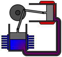
Again, the following diagrams do not show internal heat exchangers or a regenerator, which would be placed in the gas path around the displacer.
 1. Power piston (dark grey) has compressed the gas, the displacer piston (light grey) has moved so that most of the gas is adjacent to the hot heat exchanger. |
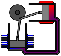
 2. The heated gas increases in pressure and pushes the power piston to the farthest limit of the power stroke. |
 3. The displacer piston now moves, shunting the gas to the cold end of the cylinder. |
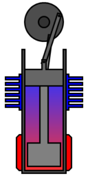
 4. The cooled gas is now compressed by the flywheel momentum. This takes less energy, since when it is cooled its pressure dropped. |
 The complete beta type Stirling cycle |
|||
[edit] Gamma Stirling
A gamma Stirling is simply a beta Stirling in which the power piston is mounted in a separate cylinder alongside the displacer piston cylinder, but is still connected to the same flywheel. The gas in the two cylinders can flow freely between them and remains a single body. This configuration produces a lower compression ratio but is mechanically simpler and often used in multi-cylinder Stirling engines.
[edit] Other types
Other Stirling configurations continue to interest engineers and inventors. Tom Peat conceived of a configuration that he likes to call a "Delta" type, although currently this designation is not widely recognized, having a displacer and two power pistons, one hot and one cold.[16]
There is also the rotary Stirling engine which seeks to convert power from the Stirling cycle directly into torque, similar to the rotary combustion engine. No practical engine has yet been built but a number of concepts, models and patents have been produced, such as the Quasiturbine engine.[17]
Another alternative is the Fluidyne engine (Fluidyne heat pump), which use hydraulic pistons to implement the Stirling cycle. The work produced by a Fluidyne engine goes into pumping the liquid. In its simplest form, the engine contains a working gas, a liquid and two non-return valves.
[edit] Free piston engines

"Free piston" Stirling engines, including those with liquid pistons and those with diaphragms as pistons. In a "free piston" device, energy may be added or removed by an electrical linear alternator, pump or other coaxial device. This sidesteps the need for a linkage, and reduces the number of moving parts. In some designs friction and wear are nearly eliminated by the use of non-contact gas bearings or very precise suspension through planar springs.
In the early 1960s, W.T. Beale invented a free piston version of the Stirling engine in order to overcome the difficulty of lubricating the crank mechanism.[18] While the invention of the basic free piston Stirling engine is generally attributed to Beale, independent inventions of similar types of engines were made by E.H. Cooke-Yarborough and C. West at the Harwell Laboratories of the UKAERE.[19][20][21][22] G.M. Benson also made important early contributions and patented many novel free-piston configurations.[23][24]
What appears to be the first mention of a Stirling cycle machine using freely moving components is a British patent disclosure in 1876.[25] This machine was envisaged as a refrigerator (i.e., the reversed Stirling cycle). The first consumer product to utilize a free piston Stirling device was a portable refrigerator manufactured by Twinbird Corporation of Japan and offered in the US by Coleman in 2004.
[edit] Thermoacoustic cycle
Thermoacoustic devices are very different from Stirling devices, although the individual path travelled by each working gas molecule does follow a real Stirling cycle. These devices include the thermoacoustic engine and thermoacoustic refrigerator. High-amplitude acoustic standing waves cause compression and expansion analogous to a Stirling power piston, while out-of-phase acoustic travelling waves cause displacement along a temperature gradient, analogous to a Stirling displacer piston. Thus a thermoacoustic device typically does not have a displacer, as found in a beta or gamma Stirling.
[edit] History
[edit] Early years

The Stirling engine (or Stirling's air engine as it was known at the time) was invented and patented by Robert Stirling in 1816.[26] It followed earlier attempts at making an air engine but was probably the first to be put to practical use when in 1818 an engine built by Stirling was employed pumping water in a quarry.[27] The main subject of Stirling's original patent was a heat exchanger which he called an "economiser" for its enhancement of fuel economy in a variety of applications. The patent also described in detail the employment of one form of the economiser in his unique closed-cycle air engine design[28] in which application it is now generally known as a 'regenerator'. Subsequent development by Robert Stirling and his brother James, an engineer, resulted in patents for various improved configurations of the original engine. Their pressurization enhancement had by 1843 sufficiently increased power output enough to drive all the machinery at a Dundee iron foundry.[29]
Though it has been disputed[30] it is widely supposed that as well as saving fuel the inventors were motivated to create a safer alternative to the steam engines of the time,[31] whose boilers frequently exploded causing many injuries and fatalities.[32][33] The need for Stirling engines to run at very high temperatures to maximize power and efficiency exposed limitations in the materials of the day and the few engines that were built in those early years suffered unacceptably frequent failures (albeit with far less disastrous consequences than a boiler explosion[34]) - for example, the Dundee foundry engine was replaced by a steam engine after three hot cylinder failures in four years.[35]
[edit] Later nineteenth century

Subsequent to the failure of the Dundee foundry engine there is no record of the Stirling brothers having any further involvement with air engine development and the Stirling engine never again competed with steam as an industrial scale power source (steam boilers were becoming safer[36] and steam engines more efficient, thus presenting less of a target to rival prime movers). However, from about 1860 smaller engines of the Stirling/hot air type were produced in substantial numbers finding applications wherever a reliable source of low to medium power was required, such as raising water or providing air for church organs.[37] These generally operated at lower temperatures so as not to tax available materials, so were relatively inefficient. But their selling point was that, unlike a steam engine, they could be operated safely by anybody capable of managing a fire.[38] Several types remained in production beyond the end of the century, but apart from a few minor mechanical improvements the design of the Stirling engine in general stagnated during this period.[39]
[edit] Twentieth century revival
During the early part of the twentieth century the role of the Stirling engine as a "domestic motor"[40] was gradually taken over by the electric motor and small internal combustion engines. Until by the late 1930s it was largely forgotten, only produced for toys and a few small ventilating fans.[41] At this time Philips was seeking to expand sales of its radios into areas where electricity was unavailable and the supply of batteries uncertain. Philips' management decided that a low-power portable generator would facilitate such sales and tasked a group of engineers at the company's research lab in Eindhoven to evaluate alternatives.
After a systematic comparison of various prime movers, the Stirling engine's quiet operation (both audibly and in terms of radio interference) and ability to run on a variety of heat sources (common lamp oil – "cheap and available everywhere" – was favoured), the team picked Stirling.[42] They were also aware that, unlike steam and internal combustion engines, virtually no serious development work had been carried out on the Stirling engine for many years and asserted that modern materials and know-how should enable great improvements.[43]

Encouraged by their first experimental engine, which produced 16 W of shaft power from a bore and stroke of 30mm × 25mm,[44] Philips began a development program. This work continued throughout World War II and by the late 1940s handed over the Type 10 to Philips' subsidiary Johan de Witt in Dordrecht to be "productionised" and incorporated into a generator set. The result, rated at 200 W from a bore and stroke of 55 mm x 27 mm, was designated MP1002CA (known as the "Bungalow set"). Production of an initial batch of 250 began in 1951, but it became clear that they could not be made at a competitive price and the advent of transistor radios with their much lower power requirements meant that the original rationale for the set was disappearing. Approximately 150 of these sets were eventually produced.[45] Some found their way into university and college engineering departments around the world[46] giving generations of students a valuable introduction to the Stirling engine.
Philips went on to develop experimental Stirling engines for a wide variety of applications and continued to work in the field until the late 1970s, but only achieved commercial success with the 'reversed Stirling engine' cryocooler. They did however take out a large number of patents and amass a wealth of information which they licensed to other companies and which formed the basis of much of the development work in the modern era.[47]
[edit] Theory of operation
[edit] The Stirling cycle

The idealized or "text book" Stirling cycle consists of four thermodynamic processes acting on the working fluid ( See diagram to right):
- Points 1 to 2, Isothermal Expansion. The expansion-space and associated heat exchanger are maintained at a constant high temperature, and the gas undergoes near-isothermal expansion absorbing heat from the hot source.
- Points 2 to 3, Constant-Volume (known as isovolumetric or isochoric) heat-removal. The gas is passed through the regenerator, where it cools transferring heat to the regenerator for use in the next cycle.
- Points 3 to 4, Isothermal Compression. The compression space and associated heat exchanger are maintained at a constant low temperature so the gas undergoes near-isothermal compression rejecting heat to the cold sink
- Points 4 to 1, Constant-Volume (known as isovolumetric or isochoric) heat-addition. The gas passes back through the regenerator where it recovers much of the heat transferred in 2 to 3, heating up on its way to the expansion space.
Theoretical efficiency equals that of the hypothetical Carnot cycle - i.e. the highest efficiency attainable by any heat engine. However, though it is useful for illustrating general principles, the text book cycle it is a long way from representing what is actually going on inside a practical Stirling engine and should not be regarded as a basis for analysis. In fact it has been argued that its indiscriminate use in many standard books on engineering thermodynamics has done a disservice to the study of Stirling engines in general.[48],[49] For a more exhaustive treatment of the 'real' Stirling cycle see main article referred to at the head of this section.
Other real-world issues reduce the efficiency of actual engines, due to limits of convective heat transfer, and viscous flow (friction). There are also practical mechanical considerations, for instance a simple kinematic linkage may be favoured over a more complex mechanism needed to replicate the idealized cycle, and limitations imposed by available materials such as non-ideal properties of the working gas, thermal conductivity, tensile strength, creep, rupture strength, and melting point.
[edit] Engine operation
Since the Stirling engine is a closed cycle, it contains a fixed mass of gas called the "working fluid", most commonly air, hydrogen or helium. In normal operation, the engine is sealed and no gas enters or leaves the engine. No valves are required, unlike other types of piston engines. The Stirling engine, like most heat engines, cycles through four main processes: cooling, compression, heating and expansion. This is accomplished by moving the gas back and forth between hot and cold heat exchangers, often with a regenerator between the heater and cooler. The hot heat exchanger is in thermal contact with an external heat source, such as a fuel burner, and the cold heat exchanger being in thermal contact with an external heat sink, such as air fins. A change in gas temperature will cause a corresponding change in gas pressure, while the motion of the piston causes the gas to be alternately expanded and compressed.
The gas follows the behaviour described by the gas laws which describe how a gas' pressure, temperature and volume are related. When the gas is heated, because it is in a sealed chamber, the pressure rises and this then acts on the power piston to produce a power stroke. When the gas is cooled the pressure drops and this means that less work needs to be done by the piston to compress the gas on the return stroke, thus yielding a net power output.
When one side of the piston is open to the atmosphere, the operation is slightly different. As the sealed volume of working gas comes in contact with the hot side, it expands, doing work on both the piston and on the atmosphere. When the working gas contacts the cold side, its pressure drops below atmospheric pressure and the atmosphere pushes on the piston and does work on the gas.
To summarize, the Stirling engine uses the temperature difference between its hot end and cold end to establish a cycle of a fixed mass of gas, heated and expanded, and cooled and compressed, thus converting thermal energy into mechanical energy. The greater the temperature difference between the hot and cold sources, the greater the thermal efficiency. The maximum theoretical efficiency is equivalent to the Carnot cycle, however the efficiency of real engines is only a fraction of this value, even in highly optimized engines.

Very low-power engines have been built which will run on a temperature difference of as little as 7 °C, for example between the palm of a hand and the surrounding air, or between room temperature and melting water ice.[50][51]
[edit] Pressurization
In most high power Stirling engines, both the minimum pressure and mean pressure of the working fluid are above atmospheric pressure. This initial engine pressurization can be realized by a pump, or by filling the engine from a compressed gas tank, or even just by sealing the engine when the mean temperature is lower than the mean operating temperature. All of these methods increase the mass of working fluid in the thermodynamic cycle. All of the heat exchangers must be sized appropriately to supply the necessary heat transfer rates. If the heat exchangers are well designed and can supply the heat flux needed for convective heat transfer, then the engine will in a first approximation produce power in proportion to the mean pressure, as predicted by the West number, and Beale number. In practice, the maximum pressure is also limited to the safe pressure of the pressure vessel. Like most aspects of Stirling engine design, optimization is multivariate, and often has conflicting requirements.[52]
[edit] Lubricants and friction

At high temperatures and pressures, the oxygen in air-pressurized crankcases, or in the working gas of hot air engines, can combine with the engine's lubricating oil and explode. At least one person has died in such an explosion.[53]
Lubricants can also clog heat exchangers, especially the regenerator. For these reasons, designers prefer non-lubricated, low-coefficient of friction materials (such as rulon or graphite), with low normal forces on the moving parts, especially for sliding seals. Some designs avoid sliding surfaces altogether by using diaphragms for sealed pistons. These are some of the factors that allow Stirling engines to have lower maintenance requirements and longer life than internal-combustion engines.
[edit] Analysis
[edit] Comparison with internal combustion engines
In contrast to internal combustion engines, Stirling engines have the potential to use renewable heat sources more easily, to be quieter, and to be more reliable with lower maintenance. They are preferred for applications that value these unique advantages, particularly if the cost per unit energy generated ($/kWh) is more important than the capital cost per unit power ($/kW). On this basis, Stirling engines are cost competitive up to about 100 kW.[54]
Compared to an internal combustion engine of the same power rating, Stirling engines currently have a higher capital cost and are usually larger and heavier. Their lower maintenance requirements make the overall energy cost comparable. The thermal efficiency is also comparable (for small engines), ranging from 15% to 30%.[54] For applications such as micro-CHP, a Stirling engine is often preferable to an internal combustion engine. Other applications include water pumping, astronautics, and electrical generation from plentiful energy sources that are incompatible with the internal combustion engine, such as solar energy, and biomass such as agricultural waste and other waste such as domestic refuse. Stirlings have also been used as a marine engine in Swedish Gotland class submarines.[55] However, Stirling engines are generally not price-competitive as an automobile engine, due to high cost per unit power, low power density and high material costs.
Basic analysis is based on the closed-form Schmidt analysis.[56][57]
[edit] Advantages of Stirling engines
- They can run directly on any available heat source, not just one produced by combustion, so they can run on heat from solar, geothermal, biological, nuclear sources or waste heat from industrial processes.
- A continuous combustion process can be used to supply heat, so most types of emissions can be reduced.
- Most types of Stirling engines have the bearing and seals on the cool side of the engine, and they require less lubricant and last longer than other reciprocating engine types.
- The engine mechanisms are in some ways simpler than other reciprocating engine types. No valves are needed, and the burner system can be relatively simple.
- A Stirling engine uses a single-phase working fluid which maintains an internal pressure close to the design pressure, and thus for a properly designed system the risk of explosion is low. In comparison, a steam engine uses a two-phase gas/liquid working fluid, so a faulty relief valve can cause an explosion.
- In some cases, low operating pressure allows the use of lightweight cylinders.
- They can be built to run quietly and without an air supply, for air-independent propulsion use in submarines.
- They start easily (albeit slowly, after warmup) and run more efficiently in cold weather, in contrast to the internal combustion which starts quickly in warm weather, but not in cold weather.
- A Stirling engine used for pumping water can be configured so that the water cools the compression space. This is most effective when pumping cold water.
- They are extremely flexible. They can be used as CHP (combined heat and power) in the winter and as coolers in summer.
- Waste heat is easily harvested (compared to waste heat from an internal combustion engine) making Stirling engines useful for dual-output heat and power systems.
[edit] Disadvantages of Stirling engines
[edit] Size and cost issues
- Stirling engine designs require heat exchangers for heat input and for heat output, and these must contain the pressure of the working fluid, where the pressure is proportional to the engine power output. In addition, the expansion-side heat exchanger is often at very high temperature, so the materials must resist the corrosive effects of the heat source, and have low creep (deformation). Typically these material requirements substantially increase the cost of the engine. The materials and assembly costs for a high temperature heat exchanger typically accounts for 40% of the total engine cost.[53]
- All thermodynamic cycles require large temperature differentials for efficient operation. In an external combustion engine, the heater temperature always equals or exceeds the expansion temperature. This means that the metallurgical requirements for the heater material are very demanding. This is similar to a Gas turbine, but is in contrast to a Otto engine or Diesel engine, where the expansion temperature can far exceed the metallurgical limit of the engine materials, because the input heat source is not conducted through the engine, so engine materials operate closer to the average temperature of the working gas.
- Dissipation of waste heat is especially complicated because the coolant temperature is kept as low as possible to maximize thermal efficiency. This increases the size of the radiators, which can make packaging difficult. Along with materials cost, this has been one of the factors limiting the adoption of Stirling engines as automotive prime movers. For other applications such as ship propulsion and stationary microgeneration systems using combined heat and power (CHP) high power density is not required.[58]
[edit] Power and torque issues
- Stirling engines, especially those that run on small temperature differentials, are quite large for the amount of power that they produce (i.e., they have low specific power). This is primarily due to the heat transfer coefficient of gaseous convection which limits the heat flux that can be attained in a typical cold heat exchanger to about 500 W/(m·K), and in a hot heat exchanger to about 500–5000 W/(m·K).[59] Compared to internal combustion engines, this makes it more challenging for the engine designer to transfer heat into and out of the working gas. Increasing the temperature differential and/or pressure allows Stirling engines to produce more power, assuming the heat exchangers are designed for the increased heat load, and can deliver the convected heat flux necessary.
- A Stirling engine cannot start instantly; it literally needs to "warm up". This is true of all external combustion engines, but the warm up time may be shorter for Stirlings than for others of this type such as steam engines. Stirling engines are best used as constant speed engines.
- Power output of a Stirling tends to be constant and to adjust it can sometimes require careful design and additional mechanisms. Typically, changes in output are achieved by varying the displacement of the engine (often through use of a swashplate crankshaft arrangement), or by changing the quantity of working fluid, or by altering the piston/displacer phase angle, or in some cases simply by altering the engine load. This property is less of a drawback in hybrid electric propulsion or "base load" utility generation where constant power output is actually desirable.
[edit] Gas choice issues
The used gas should have a low heat capacity, so that a given amount of transferred heat leads to a large increase in pressure. Considering this issue, Helium would be the best gas because of its very low heat capacity. Air is a viable working fluid[60], but the oxygen in a highly pressurized air engine can cause fatal accidents caused by lubricating oil explosions.[53] Following one such accident Philips pioneered the use of other gases to avoid such risk of explosions.
- Hydrogen's low viscosity and high thermal conductivity make it the most powerful working gas, primarily because the engine can run faster than with other gases. However, due to hydrogen bonding, and given the high diffusion rate associated with this low molecular weight gas, particularly at high temperatures, H2 will leak through the solid metal of the heater. Diffusion through carbon steel is too high to be practical, but may be acceptably low for metals such as aluminum, or even stainless steel. Certain ceramics also greatly reduce diffusion. Hermetic pressure vessel seals are necessary to maintain pressure inside the engine without replacement of lost gas. For HTD engines, auxiliary systems may need to be added to maintain high pressure working fluid. These systems can be a gas storage bottle or a gas generator. Hydrogen can be generated by electrolysis of water, the action of steam on red hot carbon-based fuel, by gasification of hydrocarbon fuel, or by the reaction of acid on metal. Hydrogen can also cause the embrittlement of metals. Hydrogen is a flammable gas, which is a safety concern, although the quantity used is very small, and it is arguably safer than other commonly used flammable gases.
- Most technically advanced Stirling engines, like those developed for United States government labs, use helium as the working gas, because it functions close to the efficiency and power density of hydrogen with fewer of the material containment issues. Helium is inert, which removes all risk of flammability, both real and perceived. Helium is relatively expensive, and must be supplied as bottled gas. One test showed hydrogen to be 5% (absolute) more efficient than helium (24% relatively) in the GPU-3 Stirling engine.[61] The researcher Allan Organ demonstrated that a well-designed air engine is theoretically just as efficient as a helium or hydrogen engine, but helium and hydrogen engines are several times more powerful per unit volume.
- Some engines use air or nitrogen as the working fluid. These gases have much lower power density (which increases engine costs), but they are more convenient to use and they minimize the problems of gas containment and supply (which decreases costs). The use of compressed air in contact with flammable materials or substances such as lubricating oil, introduces an explosion hazard, because compressed air contains a high partial pressure of oxygen. However, oxygen can be removed from air through an oxidation reaction or bottled nitrogen can be used, which is nearly inert and very safe.
- Other possible lighter-than-air gases include: methane, and ammonia.
[edit] Applications

[edit] Heating and cooling
If supplied with mechanical power, a Stirling engine can function in reverse as a heat pump for heating or cooling. Experiments have been performed using wind power driving a Stirling cycle heat pump for domestic heating and air conditioning. In the late 1930s, the Philips Corporation of the Netherlands successfully utilized the Stirling cycle in cryogenic applications.[62]
[edit] Combined heat and power
Power plants on the electric grid use fuel to produce electricity, however there are large quantities of waste heat produced which often go unused. In other situations, high-grade fuel is burned at high temperature for a low temperature application. According to the second law of thermodynamics, a heat engine can generate power from this temperature difference. In a CHP system, the high temperature primary heat enters the Stirling engine heater, then some of the energy is converted to mechanical power in the engine, and the rest passes through to the cooler, where it exits at a low temperature. The "waste" heat actually comes from engine's main cooler, and possibly from other sources such as the exhaust of the burner, if there is one.
In a combined heat and power (CHP) system, mechanical or electrical power is generated in the usual way, however, the waste heat given off by the engine is used to supply a secondary heating application. This can be virtually anything that uses low temperature heat. It is often a pre-existing energy use, such as commercial space heating, residential water heating, or an industrial process.
The power produced by the engine can be used to run an industrial or agricultural process, which in turn creates biomass waste refuse that can be used as free fuel for the engine, thus reducing waste removal costs. The overall process can be efficient and cost effective.
WhisperGen, a New Zealand firm with offices in Christchurch, has developed an "AC Micro Combined Heat and Power" Stirling cycle engine. These microCHP units are gas-fired central heating boilers which sell unused power back into the electricity grid. WhisperGen announced in 2004 that they were producing 80,000 units for the residential market in the United Kingdom. A 20 unit trial in Germany started in 2006. It is claimed that this form of microgeneration is the most cost effective method of reducing CO2 emissions., [63]
[edit] Solar power generation
Placed at the focus of a parabolic mirror a Stirling engine can convert solar energy to electricity with an efficiency better than non-concentrated photovoltaic cells, and comparable to Concentrated Photo Voltaics. On August 11, 2005, Southern California Edison announced[64] an agreement to purchase solar powered Stirling engines from Stirling Energy Systems over a twenty year period and in quantity (20,000 units) sufficient to generate 500 MW of electricity. These systems, on a 4,500 acre (19 km2) solar farm, will use mirrors to direct and concentrate sunlight onto the engines which will in turn drive generators.
[edit] Stirling cryocoolers
Any Stirling engine will also work in reverse as a heat pump; when a motion is applied to the shaft, a temperature difference appears between the reservoirs. The essential mechanical components of a Stirling cryocooler are identical to a Stirling engine. In both the engine and the heat pump, heat flows from the expansion space to the compression space; however, input work is required in order for heat to flow against a thermal gradient, specifically when the compression space is hotter than the expansion space. The external side of the expansion-space heat exchanger may be placed inside a thermally insulated compartment such as a vacuum flask. Heat is in effect pumped out of this compartment, through the working gas of the cryocooler and into the compression space. The compression space will be above ambient temperature, and so heat will flow out into the environment.
One of their modern uses is in cryogenics, and to a lesser extent, refrigeration. At typical refrigeration temperatures, Stirling coolers are generally not economically competitive with the less expensive mainstream Rankine cooling systems, even though they are typically 20% more energy efficient. However, below about −40 ° to −30 °C, Rankine cooling is not effective because there are no suitable refrigerants with boiling points this low. Stirling cryocoolers are able to "lift" heat down to −200 °C (73 K), which is sufficient to liquefy air (oxygen, nitrogen and argon). They can go as low as 40–60 K, depending on the particular design. Cryocoolers for this purpose are more or less competitive with other cryocooler technologies. The coefficient of performance at cryogenic temperatures is typically 0.04–0.05 (corresponding to a 4–5% efficiency). Empirically, the devices show a linear trend, where typically the COP = 0.0015 × Tc – 0.065, where Tc is the cryogenic temperature. At these temperatures, solid materials have lower values for specific heat, so the regenerator must be made out of unexpected materials, such as cotton.
The first Stirling cycle cryocooler was developed at Philips in the 1950s and commercialized in such places as liquid air production plants. The Philips Cryogenics business evolved until it was split off in 1990 to form the Stirling Cryogenics & Refrigeration BV, The Netherlands. This company is still active in the development and manufacturing of Stirling cryocoolers and cryogenic cooling systems.
A wide variety of smaller size Stirling cryocoolers are commercially available for tasks such as the cooling of electronic sensors and sometimes microprocessors. For this application, Stirling cryocoolers are the highest performance technology available, due to their ability to lift heat efficiently at very low temperatures. They are silent, vibration-free, and can be scaled down to small sizes, and have very high reliability and low maintenance. As of 2008, cryocoolers are considered to be the only commercially successful Stirling devices.
[edit] Heat pump
A Stirling heat pump is very similar to a Stirling cryocooler, the main difference being that it usually operates at room temperature and its principal application to date is to pump heat from the outside of a building to the inside, thus cheaply heating it.
As with any other Stirling device, heat flows from the expansion space to the compression space; however, in contrast to the Stirling engine, the expansion space is at a lower temperature than the compression space, so instead of producing work, an input of mechanical work is required by the system (in order to satisfy the second law of thermodynamics). When the mechanical work for the heat pump is provided by a second Stirling engine, then the overall system is called a "heat-driven heatpump".
The expansion side of the heat pump is thermally coupled to the heat source, which is often the external environment. The compression side of the Stirling device is placed in the environment to be heated, for example a building, and heat is "pumped" into it. Typically there will be thermal insulation between the two sides so there will be a temperature rise inside the insulated space.
Heat pumps are by far the most energy-efficient types of heating systems. Stirling heat pumps also often have a higher coefficient of performance than conventional heat pumps. To date, these systems have seen limited commercial use; however, use is expected to increase along with market demand for energy conservation, and adoption will likely be accelerated by technological refinements.
[edit] Marine engines
The Swedish shipbuilder Kockums has built 8 successful Stirling powered submarines since the late 1980s.[55] They carry compressed oxygen to allow fuel combustion whilst submerged which provides heat for the Stirling engine. They are currently used on submarines of the Gotland and Södermanland classes. They are the first submarines in the world to feature a Stirling engine air-independent propulsion (AIP) system, which extends their underwater endurance from a few days to two weeks.[citation needed] This capability has previously only been available with nuclear powered submarines.
[edit] Nuclear power
There is a potential for nuclear-powered Stirling engines in electric power generation plants. Replacing the steam turbines of nuclear power plants with Stirling engines might simplify the plant, yield greater efficiency, and reduce the radioactive byproducts. A number of breeder reactor designs use liquid sodium as coolant. If the heat is to be employed in a steam plant, a water/sodium heat exchanger is required, which raises some concern as sodium reacts violently with water. A Stirling engine eliminates the need for water anywhere in the cycle.
United States government labs have developed a modern Stirling engine design known as the Stirling Radioisotope Generator for use in space exploration. It is designed to generate electricity for deep space probes on missions lasting decades. The engine uses a single displacer to reduce moving parts and uses high energy acoustics to transfer energy. The heat source is a dry solid nuclear fuel slug and the heat sink is space itself.
[edit] Automotive engines
It is often claimed that the Stirling engine has too low a power/weight ratio, too high a cost, and too long a starting time for automotive applications. They also have complex and expensive heat exchangers. A Stirling cooler must reject twice as much heat as an Otto engine or Diesel engine radiator. The heater must be made of stainless steel, exotic alloy or ceramic to support high heater temperatures needed for high power density, and to contain hydrogen gas that is often used in automotive Stirlings to maximize power. The main difficulties involved in using the Stirling engine in an automotive application are startup time, acceleration response, shutdown time, and weight, not all of which have ready-made solutions. However, a modified Stirling engine has been recently introduced that uses concepts taken from a patented internal-combustion engine with a sidewall combustion chamber(U.S. patent 7,387,093) that promises to overcome the deficient power-density and specific-power problems, as well as the slow acceleration-response problem inherent in all Stirling engines.[65]
At least two automobiles exclusively powered by Stirling engines were developed by NASA, as well as earlier projects by the Ford Motor Company and the American Motor Company. The NASA vehicles were designed by contractors and designated MOD I and MOD II. The MOD II replaced the normal spark-ignition engine in a 1985 4-door Chevrolet Celebrity Notchback. In the 1986 MOD II Design Report (Appendix A) the results show that highway gas mileage was increased from 40 to 58 mpg and urban mileage from 26 to 33 mpg with no change in vehicle gross weight. Startup time in the NASA vehicle maxed out at 30 seconds,[citation needed] while Ford's research vehicle used an internal electric heater to jump-start the vehicle started in only a few seconds.
[edit] Electric vehicles
Many people believe that Stirling engines as part of a hybrid electric drive system can bypass all of the perceived design challenges or disadvantages of a non-hybrid Stirling automobile.
In November 2007, a prototype hybrid car using solid biofuel and a Stirling engine was announced by the Precer project in Sweden.[66]
The Manchester Union Leader reports that Dean Kamen has developed a series plug-in hybrid car using a Ford Think.[67] DEKA, Kamen's technology company in the Manchester Millyard, has recently demonstrated an electric car, the DEKA Revolt, that can go approximately 60 miles (97 km) on a single charge of its lithium battery.[67]
[edit] Aircraft engines
Stirling engines may hold theoretical promise as aircraft engines, if high power density and low cost can be achieved. They are quieter, less polluting, gain efficiency with altitude due to lower ambient temperatures, are more reliable due to fewer parts and the absence of an ignition system, produce much less vibration (airframes last longer) and safer, less explosive fuels may be used. However, the Stirling engine often has low power density compared to the commonly used Otto engine and Brayton cycle gas turbine. This issue has been a point of contention in automobiles, and this performance characteristic is even more critical in aircraft engines.
[edit] Low temperature difference engines

A low temperature difference (Low Delta T, or LTD) Stirling engine will run on any low temperature differential, for example the difference between the palm of a hand and room temperature or room temperature and an ice cube. Usually they are designed in a gamma configuration, for simplicity, and without a regenerator. They are typically unpressurized, running at pressure close to 1 atmosphere. The power produced is less than 1 W, and they are intended for demonstration purposes only. They are sold as toys and educational models.
[edit] Other recent applications
[edit] Acoustic Stirling Heat Engine
Los Alamos National Laboratory has developed an "Acoustic Stirling Heat Engine"[68] with no moving parts. It converts heat into intense acoustic power which (quoted from given source) "can be used directly in acoustic refrigerators or pulse-tube refrigerators to provide heat-driven refrigeration with no moving parts, or ... to generate electricity via a linear alternator or other electro-acoustic power transducer".
[edit] MicroCHP
WhisperGen, a New Zealand based company has developed stirling engines that can be powered by natural gas or diesel. Recently an agreement has been signed with Mondragon Corporación Cooperativa, a Spanish firm, to produce WhisperGen's microCHP and make them available for the domestic market in Europe. Some time ago E.ON UK announced a similar initiative for the UK. Stirling engines would supply the client with hot water, space heating and a surplus electric power that could be fed back into the electric grid.
However the preliminary results of an Energy Saving Trust review of the performance of the WhisperGen microCHP units suggested that their advantages were marginal at best in most homes.[69] However another author shows that that Stirling engined microgeneration is the most cost effective of various microgeneration technologies in terms of reducing CO2.[70]
[edit] Chip cooling
MSI (Taiwan) recently developed a miniature Stirling engine cooling system for personal computer chips that use the waste heat from the chip to drive a fan.[71]
[edit] Other
Think Nordic, an electric car company in Norway, is working with inventor Dean Kamen on plans to install Stirling engines in the Think City, an otherwise all-electric vehicle announced in 2007.

Dean Kamen has also developed a water distillation, cogeneration system optionally based on a Stirling engine electric generator for both electrical and heat input. The unit is patented U.S. Patent 7,340,879 with other patents pending.
[edit] See also
- Thermomechanical generator
- Beale Number
- West Number
- Schmidt number
- Fluidyne engine
- Stirling radioisotope generator
- Distributed generation
[edit] References
- ^ G. Walker (1971)
- ^ T. Finkelstein; A.J. Organ (2001),Chapters 2&3
- ^ Sleeve notes from A.J. Organ (2007)
- ^ F. Starr (2001)
- ^ C.M. Hargreaves (1991), Chapter 2.5
- ^ G. Walker (1971)
- ^ W.R. Martini (1983), p.6
- ^ G. Walker (1971)
- ^ A.J. Organ (1992), p.58
- ^ Y. Timoumi; I. Tlili; S. Ben Nasrallah (2007)
- ^ K. Hirata (1998)
- ^ W.H. Brandhorst; J.A. Rodiek (2005)
- ^ B. Kongtragool; S. Wongwises (2003)
- ^ M.Keveney (2000a)
- ^ M. Keveney (2000b)
- ^ D.Liao (a)
- ^ Quasiturbine Agence (a)
- ^ W.T. Beale (1971)
- ^ E.H. Cooke-Yarborough (1967)
- ^ E.H. Cooke-Yarborough (1970)
- ^ C.D. West (1970)
- ^ E.H. Cooke-Yarborough et al. (1974)
- ^ G.M. Benson (1973)
- ^ G.M. Benson (1977)
- ^ D. Postle (1873)
- ^ R. Sier (1999)
- ^ T. Finkelsteinl; A.J. Organ (2001), Chapter 2.2
- ^ English patent 4081 of 1816 Improvements for diminishing the consumption of fuel and in particular an engine capable of being applied to the moving (of)machinery on a principle entirely new. as reproduced in part in C.M. Hargreaves (1991), Appendix B, with full transcription of text in R. Sier (1995), p.??
- ^ R. Sier (1995), p. 93
- ^ A.J. Organ (2008a)
- ^ Excerpt from a paper presented by James Stirling in June 1845 to the Institute of Civil Engineers. As reproduced in R. Sier (1995), p.92.
- ^ A. Nesmith (1985)
- ^ R. Chuse; B. Carson (1992), Chapter 1
- ^ R. Sier (1995), p.94
- ^ T. Finkelstein; A.J. Organ (2001), p.30
- ^ Hartford Steam Boiler (a)
- ^ T. Finkelstein; A.J. Organ (2001), Chapter 2.4
- ^ The 1906 Rider-Ericsson Engine Co. catalog claimed that "any gardener or ordinary domestic can operate these engines and no licensed or experienced engineer is required".
- ^ T. Finkelstein; A.J. Organ (2001), p.64
- ^ T. Finkelstein; A.J. Organ (2001), p.34
- ^ T. Finkelstein; A.J. Organ (2001), p.55
- ^ C.M. Hargreaves (1991), pp.28–30
- ^ Philips Technical Review Vol.9 No.4 page 97 (1947)
- ^ C.M. Hargreaves (1991), Fig. 3
- ^ C.M. Hargreaves (1991), p.61
- ^ Letter dated March 1961 from Research and Control Instruments Ltd. London WC1 to North Devon Technical College, offering "remaining stocks...... to institutions such as yourselves..... at a special price of £75 nett"
- ^ C.M. Hargreaves (1991), p.77
- ^ T. Finkelstein; A.J. Organ (2001), Page 66 & 229
- ^ A.J. Organ (1992), Chapter 3.1 - 3.2
- ^ K. Hirata (a), "This engine is running on PALMTOP! by using heat of Palm. Then temperature difference of it is 7K"
- ^ PASCO (1995), p.??
- ^ A.J. Organ (1997), p.??
- ^ a b c C.M. Hargreaves (1991), p.??
- ^ a b WADE (a)
- ^ a b Kockums (a)
- ^ Z. Herzog (2008)
- ^ K. Hirata (1997)
- ^ BBC News (2003), "The boiler is based on the Stirling engine, dreamed up by the Scottish inventor Robert Stirling in 1816. [...] The technical name given to this particular use is Micro Combined Heat and Power or Micro CHP."
- ^ A.J. Organ (1997), p.??
- ^ A.J. Organ (2008b)
- ^ L.G. Thieme (1981)
- ^ C.M. Hargreaves (1991), p.63
- ^ http://www.claverton-energy.com/what-is-microgeneration.html
- ^ Pure Energy Systems (2005)
- ^ J. Hasci (2008)
- ^ Precer Group (a)
- ^ a b S.K. Wickham (2008)
- ^ S. Backhaus; G. Swift (2003)
- ^ Carbon Trust (2007)
- ^ http://www.claverton-energy.com/what-is-microgeneration.html
- ^ MSI (2008)
[edit] Bibliography
- S.D. Allan (2005). "World's Largest Solar Installation to use Stirling Engine Technology". Pure Energy Systems News. http://pesn.com/2005/08/11/9600147_Edison_Stirling_largest_solar/. Retrieved on 2009-01-19.
- S. Backhaus; G. Swift (2003). "Acoustic Stirling Heat Engine: More Efficient than Other No-Moving-Parts Heat Engines". Los Alamos National Laboratory. http://www.lanl.gov/mst/engine/. Retrieved on 2009-01-19.
- BBC News (2003). "Power from the people". http://news.bbc.co.uk/2/hi/programmes/working_lunch/3231549.stm. Retrieved on 2009-01-19.
- W.T. Beale (1971). "Stirling Cycle Type Thermal Device", US patent 3552120. Granted to Research Corp, 5 January 1971.
- G.M. Benson (1977). "Thermal Oscillators", US patent 4044558. Granted to New Process Ind, 30 August 1977 .
- G.M. Benson (1973). "Thermal Oscillators". Proceedings of the 8th IECEC: 182–189, Philadelphia: ASME.
- H.W. Brandhorst; J.A. Rodiek (2005). "A 25 kW Solar Stirling Concept for Lunar Surface Exploration". International Astronautics Federation Procedings of the 56th International Astronautical Congress. IAC-05-C3.P.05.
- Carbon Trust (2007). "Micro-CHP Accelerator - Interim Report - Executive summary". http://www.carbontrust.co.uk/publications/publicationdetail.htm?productid=CTC727. Retrieved on 2009-01-19.
- E.H. Cooke-Yarborough; E. Franklin; J. Geisow; R. Howlett; C.D. West (1974). "Harwell Thermo-Mechanical Generator". Proceedings of the 9th IECEC: 1132–1136, San Francisco: ASME. Bibcode: 1974iece.conf.1132C.
- E.H. Cooke-Yarborough (1970). "Heat Engines", US patent 3548589. Granted to Atomic Energy Authority UK, 22 December 1970.
- E.H. Cooke-Yarborough (1967). "A Proposal for a Heat-Powered Nonrotating Electrical Alternator", Harwell Memorandum AERE-M881.
- R. Chuse; B. Carson (1992). Pressure Vessels, The ASME Code Simplified. McGraw–Hill. ISBN 0-070-10939-7.
- T. Finkelstein; A.J. Organ (2001). Air Engines. Professional Engineering Publishing. ISBN 1-86058-338-5.
- C.M. Hargreaves (1991). The Philips Stirling Engine. Elsevier Science. ISBN 0-444-88463-7.
- J. Harrison (2008). "What is micro generation?". Claverton Energy Research Group. http://www.claverton-energy.com/what-is-microgeneration.html. Retrieved on 2009-01-19.
- Hartford Steam Boiler (a). "Hartford Steam Boiler: Steam Power and the Industrial Revolution". http://www.hsb.com/about.asp?id=50. Retrieved on 2009-01-18.
- J. Hasci (2008). "Modified Stirling Engine With Greater Power Density". Create the Future Design Contest. NASA & SolidWorks. http://www.createthefuturecontest.com/pages/view/entriesdetail.html?entryID=1329. Retrieved on 2009-01-19.
- Z. Herzog (2008). "Schmidt Analysis". http://mac6.ma.psu.edu/stirling/simulations/isothermal/schmidt.html. Retrieved on 2009-01-18.
- K. Hirata (1998). "Design and manufacturing of a prototype engine". National Maritime Research Institute. http://www.nmri.go.jp/eng/khirata/stirling/docpaper/sekkeie.html. Retrieved on 2009-01-18.
- K. Hirata (1997). "Schmidt Theory For Stirling Engines". http://www.bekkoame.ne.jp/~khirata/academic/schmidt/schmidt.htm. Retrieved on 2009-01-18.
- K. Hirata (a). "Palm Top Stirling Engine". http://www.bekkoame.ne.jp/~khirata/academic/kiriki/models/plm_top.html. Retrieved on 2009-01-18.
- M. Keveney (2000a). "Two Cylinder Stirling Engine". animatedengines.com. http://www.animatedengines.com/vstirling.shtml. Retrieved on 2009-01-18.
- M. Keveney (2000b). "Single Cylinder Stirling Engine". animatedengines.com. http://www.animatedengines.com/stirling.shtml. Retrieved on 2009-01-18.
- Kockums. "The Stirling Engine: An Engine for the Future". http://www.kockums.se/products/kockumsstirlingm.html. Retrieved on 2009-01-18.
- B. Kongtragool; S. Wongwises (2003). "A review of solar-powered Stirling engines and low temperature differential Stirling engines". Renewable and Sustainable Energy Reviews 7 (2): 131–154. doi:.
- D. Liao (a). "The Working Principles". http://www.logicsys.com.tw/wrkbas.htm. Retrieved on 2009-01-18.
- W.R. Martini (1983). "Stirling Engine Design Manual (2nd ed)" (17.9 MB PDF). NASA. http://ntrs.nasa.gov/archive/nasa/casi.ntrs.nasa.gov/19830022057_1983022057.pdf. Retrieved on 2009-01-19.
- Micro-Star International (2008). "World's First Powerless Air Cooler on a Mainboard!". http://global.msi.com.tw/index.php?func=newsdesc&news_no=591. Retrieved on 2009-01-19.
- A. Nesmith (1985). "A Long, Arduous March Toward Standardization". Smithsonian Magazine. http://www.asme.org/Communities/History/Resources/Long_Arduous_March_Toward.cfm. Retrieved on 2009-01-18.
- A.J. Organ (2008a). "1818 and All That". Communicable Insight. http://web.me.com/allan.j.o/Communicable_Insight/1818_and_all_that.html. Retrieved on 2009-01-18.
- A.J. Organ (2008b). "Why Air?". Communicable Insight. http://web.me.com/allan.j.o/Communicable_Insight/Why_air.html. Retrieved on 2009-01-18.
- A.J. Organ (2007). The Air Engine: Stirling Cycle Power for a Sustainable Future. Woodhead Publishing. ISBN 1-845-69231-4.
- A.J. Organ (1997). The Regenerator and the Stirling Engine. Wiley. ISBN 1-860-58010-6.
- A.J. Organ (1992). Thermodynamics and Gas Dynamics of the Stirling Cycle Machine. Cambridge University Press. ISBN 0-521041363-x.
- PASCO Scientific (1995). "Instruction Manual and Experiment Guide for the PASCO scientific Model SE-8575". http://store.pasco.com/pascostore/showdetl.cfm?&DID=9&Product_ID=50750&groupID=477&page=Manuals. Retrieved on 2009-01-18. (the link to the PDF manual is at the bottom of the page)
- D. Postle (1873). "Producing Cold for Preserving Animal Food", British Patent 709, granted 26 February 1873.
- Precer Group (a). "Solid Biofuel-Powered Vehicle Technology". http://www.precer.se/Files/Precer%20Data%20Sheet%20D.pdf. Retrieved on 2009-01-19.
- Quasiturbine Agence (a). "Quasiturbine Stirling – Hot Air Engine". http://quasiturbine.promci.qc.ca/ETypeStirling.htm. Retrieved on 2009-01-18.
- R. Sier (1999). Hot Air Caloric and Stirling Engines: A History. 1 (1st (Revised) ed.). L.A. Mair. ISBN 0-9526417-0-4.
- R. Sier (1995). Reverend Robert Stirling D.D: A Biography of the Inventor of the Heat Economiser and Stirling Cycle Engine. L.A Mair. ISBN 0-9526417-0-4.
- F. Starr (2001). "Power for the People: Stirling Engines for Domestic CHP". Ingenia (8): 27–32. http://www.ingenia.org.uk/ingenia/issues/issue8/Starr.pdf. Retrieved on 2009-01-18.
- WADE (a). "Stirling Engines". http://www.localpower.org/deb_tech_se.html. Retrieved on 2009-01-18.
- L.G. Thieme (1981). "High-power baseline and motoring test results for the GPU-3 Stirling engine" (14.35 MB PDF). NASA. http://ntrs.nasa.gov/archive/nasa/casi.ntrs.nasa.gov/19810023544_1981023544.pdf. Retrieved on 2009-01-19.
- Y. Timoumi; I. Tlili; S.B. Nasrallah (2008). "Performance Optimization of Stirling Engines". Renewable Energy 33 (9): 2134–2144. doi:.
- G. Walker (1971). "Lecture notes for Stirling engine seminar", University of Bath. Reprinted in 1978.
- C.D. West (1970). "Hydraulic Heat Engines", Harwell Momorandum AERE-R6522.
- S.K. Wickham (2008). "Kamen's Revolt". Union Leader. http://www.unionleader.com/article.aspx?articleId=1b081989-f67b-458e-8e42-913c8568fb36. Retrieved on 2009-01-19.
[edit] Further reading
- R.C. Belaire (1977). "Device for decreasing the start-up time for stirling engines", US patent 4057962. Granted to Ford Motor Company, 15 November 1977.
- P.H. Ceperley (1979). "A pistonless Stirling engine—The traveling wave heat engine". Journal of the Acoustical Society of America 66 (5): 1508–1513. doi:.
- P. Fette. "About the Efficiency of the Regenerator in the Stirling Engine and the Function of the Volume Ratio Vmax/Vmin". http://home.germany.net/101-276996/etatherm.htm. Retrieved on 2009-01-19.
- P. Fette. "A Twice Double Acting α-Type Stirling Engine Able to Work with Compound Fluids Using Heat Energy of Low to Medium Temperatures". http://home.germany.net/101-276996/english.htm. Retrieved on 2009-01-19.
- D. Haywood. "An Introduction to Stirling-Cycle Analysis" (PDF). http://www.mech.canterbury.ac.nz/documents/sc_intro.pdf. Retrieved on 2009-01-19.
- Z. Herzog (2006). "Stirling Engines". written at Mont Alto. Pennsylvania State University. http://mac6.ma.psu.edu/stirling/. Retrieved on 2009-01-19.
- F. Kyei-Manu; A. Obodoako (2005). "Solar Stirling-Engine Water Pump Proposal Draft" (PDF). http://www.engin.swarthmore.edu/academics/courses/e90/2005_6/E90Proposal/FK_AO.pdf. Retrieved on 2009-01-19.
- Lund University, Department of Energy Science: Division of Combustion Engines. "Stirling Engine Research". http://www.vok.lth.se/~ce/Research/stirling/stirling_en.htm. Retrieved on 2009-01-19.
- N.P. Nightingale (1986). "NASA Automotive Stirling Engine MOD II Design Report". NASA. http://ntrs.nasa.gov/archive/nasa/casi.ntrs.nasa.gov/19880002196_1988002196.pdf. Retrieved on 2009-01-19.
- D. Phillips (1904). "Why Aviation Needs the Stirling Engine". http://www.airsport-corp.com/fourpartstirling.html. Retrieved on 2009-01-19.
[edit] External links
| Wikimedia Commons has media related to: Stirling engine |
- I. Urieli (2008). Stirling Cycle Machine Analysis 2008 Winter Syllabus
- Refrigerator animation
- The Rotary Piston Array Machine
- Simple Performance Prediction Method for Stirling Engine
- Stirling Engines at the Open Directory Project
|
|||||||||||||||||||
|
||||||||||||||||||||

