Diode bridge
From Wikipedia, the free encyclopedia

A diode bridge or bridge rectifier is an arrangement of four diodes in a bridge configuration that provides the same polarity of output voltage for either polarity of input voltage. When used in its most common application, for conversion of alternating current (AC) input into direct current (DC) output, it is known as a bridge rectifier. A bridge rectifier provides full-wave rectification from a two-wire AC input, resulting in lower cost and weight as compared to a center-tapped transformer design.[1]
The essential feature of a diode bridge is that the polarity of the output is the same regardless of the polarity at the input. The diode bridge circuit is also known as the Graetz circuit after its inventor, physicist Leo Graetz.
Contents |
[edit] Basic operation
According to the conventional model of current flow originally established by Benjamin Franklin and still followed by most engineers today, current is assumed to flow through electrical conductors from the positive to the negative pole.[2] In actuality, free electrons in a conductor nearly always flow from the negative to the positive pole. In the vast majority of applications, however, the actual direction of current flow is irrelevant. Therefore, in the discussion below the conventional model is retained.
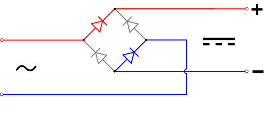
In the diagrams below, when the input connected to the left corner of the diamond is positive, and the input connected to the right corner is negative, current flows from the upper supply terminal to the right along the red (positive) path to the output, and returns to the lower supply terminal via the blue (negative) path.
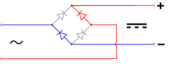
When the input connected to the left corner is negative, and the input connected to the right corner is positive, current flows from the lower supply terminal to the right along the red path to the output, and returns to the upper supply terminal via the blue path.[3]

In each case, the upper right output remains positive and lower right output negative. Since this is true whether the input is AC or DC, this circuit not only produces a DC output from an AC input, it can also provide what is sometimes called "reverse polarity protection". That is, it permits normal functioning of DC-powered equipment when batteries have been installed backwards, or when the leads (wires) from a DC power source have been reversed, and protects the equipment from potential damage caused by reverse polarity.
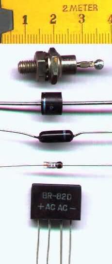
Prior to the availability of integrated circuits, a bridge rectifier was constructed from "discrete components", i.e., separate diodes. Since about 1950, a single four-terminal component containing the four diodes connected in a bridge configuration became a standard commercial component and is now available with various voltage and current ratings.
[edit] Output smoothing
For many applications, especially with single phase AC where the full-wave bridge serves to convert an AC input into a DC output, the addition of a capacitor may be desired because the bridge alone supplies an output of fixed polarity but continuously varying or "pulsating" magnitude (see diagram above).[1]
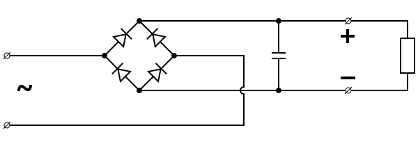
The function of this capacitor, known as a reservoir capacitor (or smoothing capacitor) is to lessen the variation in (or 'smooth') the rectified AC output voltage waveform from the bridge. One explanation of 'smoothing' is that the capacitor provides a low impedance path to the AC component of the output, reducing the AC voltage across, and AC current through, the resistive load. In less technical terms, any drop in the output voltage and current of the bridge tends to be canceled by loss of charge in the capacitor. This charge flows out as additional current through the load. Thus the change of load current and voltage is reduced relative to what would occur without the capacitor. Increases of voltage correspondingly store excess charge in the capacitor, thus moderating the change in output voltage / current.
The simplified circuit shown has a well-deserved reputation for being dangerous, because, in some applications, the capacitor can retain a lethal charge after the AC power source is removed. If supplying a dangerous voltage, a practical circuit should include a reliable way to safely discharge the capacitor. If the normal load cannot be guaranteed to perform this function, perhaps because it can be disconnected, the circuit should include a bleeder resistor connected as close as practical across the capacitor. This resistor should consume a current large enough to discharge the capacitor in a reasonable time, but small enough to minimize unnecessary power waste.
Because a bleeder sets a minimum current drain, the regulation of the circuit, defined as percentage voltage change from minimum to maximum load, is improved. However in many cases the improvement is of insignificant magnitude.
The capacitor and the load resistance have a typical time constant τ = RC where C and R are the capacitance and load resistance respectively. As long as the load resistor is large enough so that this time constant is much longer than the time of one ripple cycle, the above configuration will produce a smoothed DC voltage across the load.
In some designs, a series resistor at the load side of the capacitor is added. The smoothing can then be improved by adding additional stages of capacitor–resistor pairs, often done only for sub-supplies to critical high-gain circuits that tend to be sensitive to supply voltage noise.
The idealized waveforms shown above are seen for both voltage and current when the load on the bridge is resistive. When the load includes a smoothing capacitor, both the voltage and the current waveforms will be greatly changed. While the voltage is smoothed, as described above, current will flow through the bridge only during the time when the input voltage is greater than the capacitor voltage. For example, if the load draws an average current of n Amps, and the diodes conduct for 10% of the time, the average diode current during conduction must be 10n Amps. This non-sinusoidal current leads to harmonic distortion and a poor power factor in the AC supply.
In a practical circuit, when a capacitor is directly connected to the output of a bridge, the bridge diodes must be sized to withstand the current surge that occurs when the power is turned on at the peak of the AC voltage and the capacitor is fully discharged. Sometimes a small series resistor is included before the capacitor to limit this current, though in most applications the power supply transformer's resistance is already sufficient.
Output can also be smoothed using a choke and second capacitor. The choke tends to keep the current (rather than the voltage) more constant. This design is not generally used in modern equipment due to the high cost of an effective choke compared to a resistor and capacitor.
Some early console radios created the speaker's constant field with the current from the high voltage ("B +") power supply, which was then routed to the consuming circuits, (permanent magnets were then too weak for good performance) to create the speaker's constant magnetic field. The speaker field coil thus performed 2 jobs in one: it acted as a choke, filtering the power supply, and it produced the magnetic field to operate the speaker.
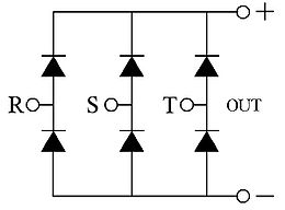
[edit] Polyphase diode bridges
The diode bridge can be generalized to rectify polyphase AC inputs. For example, for a three-phase AC input, a half-wave rectifier consists of three diodes, but a full-wave bridge rectifier consists of six diodes.


[edit] See also
[edit] References
- ^ a b Horowitz, Paul and Winfield Hill, The Art of Electronics, Second Ed., Cambridge University Press, 1989, pp. 44-47, ISBN 0521370957.
- ^ Stutz, Michael (stutz@dsl.org), "Conventional versus electron flow", All About Circuits, Vol. 1, Chapter 1, 2000.
- ^ Sears, Francis W., Mark W. Zemansky and Hugh D. Young, University Physics, Sixth Ed., Addison-Wesely Publishing Co., Inc., 1982, p. 685.
| Wikimedia Commons has media related to: Bridge rectifiers |

