555 timer IC
From Wikipedia, the free encyclopedia
|
|
This article needs additional citations for verification. Please help improve this article by adding reliable references (ideally, using inline citations). Unsourced material may be challenged and removed. (June 2008) |
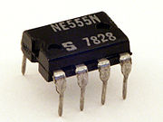

The 555 is an integrated circuit (chip) implementing a variety of timer and multivibrator applications. The IC was designed and invented by Hans R. Camenzind. It was designed in 1970 and introduced in 1971 by Signetics (later acquired by Philips). The original name was the SE555/NE555 and was called "The IC Time Machine".[1] The 555 gets its name from the three 5-kohm resistors used in typical early implementations.[2] It is still in wide use, thanks to its ease of use, low price and good stability. As of 2003[update], 1 billion units are manufactured every year.[citation needed]
The 555 timer is one of the most popular and versatile integrated circuits ever produced. Depending on the manufacturer, it includes over 20 transistors, 2 diodes and 15 resistors on a silicon chip installed in an 8-pin mini dual-in-line package (DIP-8).[3]
The 556 is a 14-pin DIP that combines two 555s on a single chip.
The 558 is a 16-pin DIP that combines four slightly modified 555s on a single chip (DIS & THR are connected internally, TR is falling edge sensitive instead of level sensitive).
Also available are ultra-low power versions of the 555 such as the 7555 and TLC555.[4] The 7555 requires slightly different wiring using fewer external components and less power.
The 555 has three operating modes:
- Monostable mode: in this mode, the 555 functions as a "one-shot". Applications include timers, missing pulse detection, bouncefree switches, touch switches, Frequency Divider,Capacitance Measurement, Pulse Width Modulation (PWM) etc
- Astable - Free Running mode: the 555 can operate as an oscillator. Uses include LED and lamp flashers, pulse generation, logic clocks, tone generation, security alarms, pulse position modulation, etc.
- Bistable mode or Schmitt trigger: the 555 can operate as a flip-flop, if the DIS pin is not connected and no capacitor is used. Uses include bouncefree latched switches, etc.
Contents |
[edit] Usage

The connection of the pins is as follows:
| Nr. | Name | Purpose |
|---|---|---|
| 1 | GND | Ground, low level (0V) |
| 2 | TR | A short pulse high → low on the trigger starts the timer |
| 3 | Q | During a timing interval, the output stays at +VCC |
| 4 | R | A timing interval can be interrupted by applying a reset pulse to low (0V) |
| 5 | CV | Control voltage allows access to the internal voltage divider (2/3 VCC) |
| 6 | THR | The threshold at which the interval ends (it ends if U.thr → 2/3 VCC) |
| 7 | DIS | Connected to a capacitor whose discharge time will influence the timing interval |
| 8 | V+, VCC | The positive supply voltage which must be between 3 and 15 V |

[edit] Monostable mode
In the monostable mode, the 555 timer acts as a “one-shot” pulse generator. The pulse begins when the 555 timer receives a trigger signal. The width of the pulse is determined by the time constant of an RC network, which consists of a capacitor (C) and a resistor (R). The pulse ends when the charge on the C equals 2/3 of the supply voltage. The pulse width can be lengthened or shortened to the need of the specific application by adjusting the values of R and C.[5]
The pulse width of time t is given by
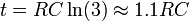
which is the time it takes to charge C to 2/3 of the supply voltage. See RC circuit for an explanation of this effect.
The relationships of the trigger signal, the voltage on the C and the pulse width are shown below:

[edit] Astable mode

In astable mode, the 555 timer outputs a continuous stream of rectangular pulses having a specified frequency. A resistor (call it R1) is connected between Vcc and the discharge pin (pin 7) and another (R2) is connected between the discharge pin (pin 7) and the trigger (pin 2) and threshold (pin 6) pins that share a common node. Hence the capacitor is charged through R1 and R2, and discharged only through R2, since pin 7 has low impedance to ground during output low intervals of the cycle, therefore discharging the capacitor. The use of R2 is mandatory, since without it the high current spikes from the capacitor may damage the internal discharge transistor.
In the astable mode, the frequency of the pulse stream depends on the values of R1, R2 and C:

The high time from each pulse is given by

and the low time from each pulse is given by

where R1 and R2 are the values of the resistors in ohms and C is the value of the capacitor in farads.
[edit] Specifications
These specifications apply to the NE555. Other 555 timers can have better specifications depending on the grade (military, medical, etc).
| Supply voltage (VCC) | 4.5 to 15 V |
| Supply current (VCC = +5 V) | 3 to 6 mA |
| Supply current (VCC = +15 V) | 10 to 15 mA |
| Output current (maximum) | 200 mA |
| Power dissipation | 600 mW |
| Operating temperature | 0 to 70 °C |
[edit] Derivatives
Many pin-compatible variants, including CMOS versions, have been built by various companies. There also exists bigger packages with two or four timers on the same chip. The 555 is also known under the following type numbers:
| Manufacturer | Model | Remark |
|---|---|---|
| ECG Philips | ECG955M | |
| Exar | XR-555 | |
| Fairchild Semiconductor | NE555/KA555 | |
| Harris | HA555 | |
| IK Semicon | ILC555 | CMOS from 2V |
| Intersil | SE555/NE555/ICM7555 | |
| Lithic Systems | LC555 | |
| Maxim | ICM7555 | CMOS from 2V |
| Motorola | MC1455/MC1555 | |
| National Semiconductor | LM1455/LM555/LM555C | |
| National Semiconductor | LMC555 | CMOS from 1.5V |
| NTE Sylvania | NTE955M | |
| Raytheon | RM555/RC555 | |
| RCA | CA555/CA555C | |
| STMicroelectronics | NE555N/ K3T647 | |
| Texas Instruments | SN52555/SN72555; TLC555 | latter: CMOS from 2V |
| USSR | K1006ВИ1 | |
| Zetex | ZSCT1555 | down to 0.9V |
[edit] Dual timer 556
The dual version is called 556. It features two complete 555s in a 14 pin DIL package.
[edit] Quad timer 558
The quad version is called 558 and has 16 pins. To fit four 555's into a 16 pin package the control voltage and reset lines are shared by all four modules. Also for each module the discharge and threshold are internally wired together and called timing.
[edit] Example applications
[edit] Joystick interface circuit using quad timer 558

The original IBM personal computer used a quad timer 558 in monostable (or "one-shot") mode to interface up to two joysticks to the host computer. (See [7]PC analogue joystick interface.) In the joystick interface circuit of the IBM PC, the capacitor (C) of the RC network (see Monostable Mode above) was generally a 10 nF capcitor. The resistor (R) of the RC network consisted of the potentiometer inside the joystick along with an external resistor of 2.2 kilohms.[8] The joystick potentiometer acted as a variable resistor. By moving the joystick, the resistance of the joystick increased from a small value up to about 100 kilohms. The joystick operated at 5 V.[9]
Software running in the host computer started the process of determining the joystick position by writing to a special address (ISA bus I/O address 201h).[10], [11] This would result in a trigger signal to the quad timer, which would cause the capacitor (C) of the RC network to begin charging and cause the quad timer to output a pulse. The width of the pulse was determined by how long it took the C to charge up to 2/3 of 5 V (or about 3.33 V), which was in turn determined by the joystick position.[12], [13]
Software running in the host computer measured the pulse width to determine the joystick position. A wide pulse represented the full-right joystick position, for example, while a narrow pulse represented the full-left joystick position.[14]
The relationship between the trigger signal, capacitor voltage and the output pulse representing joystick position is shown to the right.
[edit] References
- ^ van Roon, Tony, "555 Timer Tutorial," p. 1.
- ^ Scherz, Paul, "Practical Electronics for Inventors," p. 589.
- ^ van Roon, Tony, "555 Timer Tutorial," Fig. 3 and related text.
- ^ Jung, Walter G., "IC Timer Cookbook, Second Edition," pp. 40-41.
- ^ van Roon, Tony, "555 Timer Tutorial," at "Monostable Mode"
- ^ van Roon, Tony, "555 Timer Tutorial," at "Astable operation"
- ^ Engdahl, Tomi, "PC analogue joystick interface," at "Introduction"
- ^ Engdahl, Tomi, "PC analogue joystick interface," at "Circuit diagram of PC joystick interface"
- ^ Engdahl, Tomi, "PC analogue joystick interface," at "Joystick construction"
- ^ Engdahl, Tomi, "PC analogue joystick interface," at "How PC joystick port hardware works"
- ^ Eggebrecht, Lewis C., "Interfacing to the IBM Personal Computer," at p. 197
- ^ Engdahl, Tomi, "PC analogue joystick interface," at "Introduction" and "Resistive analogue inputs (joystick position)"
- ^ Eggebrecht, Lewis C., "Interfacing to the IBM Personal Computer," at pp. 197-99
- ^ Engdahl, Tomi, "PC analogue joystick interface," at "Joystick construction"
[edit] External links
| Wikimedia Commons has media related to: 555 timer IC |
- 555 Timer Circuits - the Astable, Monostable and Bistable
- 555 Timer Tutorial
- 555 and 556 Timer Circuits
- 555 Timer Pin configurations
- Data Sheet (Fairchild) (PDF)
- Java simulation of 555 oscillator circuit
- 1972 Signetics NE555 datasheet (PDF)
- 555 timer info
- Using NE 555 as a Temperature DSP
- Frequency and duty cycle calculator for astable multivibrators based on the NE555
- How to build a camera intervalometer using a 555

