1-Wire
From Wikipedia, the free encyclopedia
1-Wire is a registered trademark of Dallas Semiconductor Corp.[1] for a device communications bus system designed by Dallas Semiconductor that provides low-speed data, signaling and power over a single signal, albeit using two wires, one for ground, one for power and data. 1-Wire is similar in concept to I²C, but with lower data rates and longer range. It is typically used to communicate with small inexpensive devices such as digital thermometers and weather instruments. A network of 1-Wire devices with an associated master device is called a "MicroLan", that term being trademarked by Dallas.
One of the attractive features of the bus is that a device only needs two wires: data and ground. To accomplish this, the integrated circuit includes an 800 pF capacitor to power it from the data line. Some of the devices are available in tiny cans that look like small capacitors or watch batteries, in which packaging they are called iButtons.
1-Wire devices are also found mounted on printed circuit boards, with or without a 1-Wire controller. Sometimes the PCB is only there to support the 1-wire device, but in many commercial applications, the 1-Wire device is just one of the chips creating the solution to some need. They are sometimes present in laptop and cellphone battery packs, for instance.
Some laboratory systems and other data acquisition and control systems connect to 1-wire devices using cords with modular connectors or with CAT-5 cable, with the devices themselves mounted in a socket, incorporated in a small PCB, or attached to the object being monitored. In such systems, RJ11 (6P2C or 6P4C modular plugs, commonly used for telephones) are popular.
Systems of sensors and actuators can be built by wiring together 1-Wire components, each including all of the logic needed to operate on the 1-Wire bus. Examples include temperature loggers, timers, voltage and current sensors, battery monitors, and memory. These can be connected to a PC using a bus converter. USB, RS-232 Serial, and parallel port interfaces are popular solutions for connecting the MicroLan to the host PC. MicroLans also interface to microcontrollers, such as the Arduino, Parallax BASIC Stamp and the Microchip PIC family.
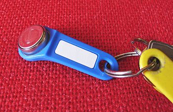
The iButton (also known as the Dallas Key) is a mechanical packaging standard that places a 1-Wire component inside a small stainless steel "button" similar to a disk-shaped battery. iButtons are connected to 1-Wire bus systems by means of sockets with contacts which touch the "lid" and "base" of the canister. The connection can be fleeting, comparable to a thumb being scanned by a fingerprint reader. Alternatively, the connection can be semi-permanent with a different socket type; the iButton clips into it, but is easily removed.
The JavaRing, a ring-mounted iButton with a Java Virtual Machine (compatible with the Java Card 2.0 specification) within was presented to the attendants of the JavaOne 1998 conference[2].
Each individual 1-Wire chip has a unique code buried within it. Every chip has a different number. This feature makes the chips, especially in an iButton package, ideal as "keys", in sense of the device which opens a lock. There are iButton solutions to securing premises, arming and deactivating burglar alarms and other uses. There are also systems for "unlocking" less obvious "secure areas". For example, iButtons can be used to authenticate computer system users, or with "time clock" systems.
Contents |
[edit] Use of the bus
In any MicroLan, there is always one (and only one) master in overall charge. That may be a PC, or a microcontroller. The master initiates activity on the bus, simplifying the avoidance of collisions on the bus. Protocols are built into the software to detect collisions. After a collision, the master tries again to effect the required communication.
The Dallas 1-Wire network is physically implemented as an open drain master device connected to one or more open drain slaves[3] . A single pull up resistor is common to all devices and acts to pull the bus up to 3 or 5 volts, and may provide power to the slave devices. Communication occurs when a master or slave asserts the bus low i.e., connects the pull up resistor to ground through its output MOSFET. Specific 1-Wire driver and bridge chips are also available. Datarates of 16.3 kbit/s can be achieved. There is also an overdrive mode which speeds up the communication by a factor of 10.
The master starts a transmission with a "reset" pulse, which pulls the wire to 0 volts for 480 µs. This resets every slave device on the bus, probably by depriving them all of power. After that, any slave device, if present, shows that it exists with a "presence" pulse: it holds the wire to ground for at least 60 µs after the master release the bus.
To send a "1", the bus master software sends a very brief (1 - 15 µs) low pulse. To send a "0", the software sends a 60 µs low pulse. The falling (negative) edge of the pulse is used to start a monostable multivibrator in the slave device. The multivibrator in the slave clocks to read the data line about 30 µs after the falling edge. The slave's multivibrator unavoidably has analog tolerances that affect its timing accuracy, which is why the output pulses have to be 60 µs long, and the starting pulse can't be longer than 15 µs.
If a parallel port is inconvenient or the operating system interferes with the timing, an UART running at 100 kbit/s with a few resistors and special software can produce and sense acceptable 1-wire pulses. Serial or USB "bridge" chips are also available that handle the timing and waveform requirements of the 1-Wire bus, and are particularly useful in utilizing long (greater than 100 m) cables effectively. Up to 300 meter long buses consisting of simple twistedpair telephone cable has been tested by the manufacturer. It will however require adjustment of pull-up resistances from say 5kΩ to 1 kΩ.
When receiving data, the master sends a 1-15 µs 0 volt pulse to start each bit. If the transmitting slave unit wants to send a "1", it does nothing, and the wire goes immediately up to the pulled-up voltage. If the transmitting slave wants to send a "0", it pulls the data line to ground for 60 µs.
The basic sequence is a reset pulse followed by an 8-bit command, and then data is sent or received in groups of 8-bits.
When a sequence of data is being transferred, errors can be detected with an 8-bit CRC (weak data protection).
Many devices can share the same bus. Each device on the bus has a unique 64-bit serial number. The least significant byte of the serial number is an 8-bit number that tells the type of the device. The most significant byte is a standard (for the 1-wire bus) 8-bit CRC. [4]
There are several standard broadcast commands, and commands addressed to particular devices. The master can send a selection command, and then the address of a particular device, and then the next command is executed only by the selected device.
The bus also has an algorithm to recover the address of every device on the bus. Since the address includes the device type and a CRC, recovering the address roster also produces a reliable inventory of the devices on the bus. The 64-bit address space is searched as a binary tree. Allowing up to 75 devices to be found per second.
To find the devices, the master broadcasts an enumeration command, and then an address, "listening" after each bit of an address. If a slave has all the address bits so far, it returns a 0. The master uses this simple behavior to search systematically for valid sequences of address bits. The process is much faster than a brute force search of all possible 64-bit numbers because as soon as an invalid bit is detected, all subsequent address bits are known to be invalid. An enumeration of 10 or 15 devices finishes very quickly. The location of devices on the bus is sometimes important as well. For these situations, the manufacturer has a special device that either passes through the bus, or switches it off. Software can therefore explore sequential "bus domains." [4]
[edit] Example communication with a device
The following signals were generated by an FPGA, which was the master for the communication with a DS2432 (EEPROM) chip, and measured with a logic analyzer. High on the 1-wire output means that the output of the FPGA is in tri-state mode and the 1-wire device can pull down the bus. Low means that the FPGA pulls down the bus. The 1-wire input is the measured bus signal. On input sample time high, the FPGA samples the input for detecting the device response and receiving bits.

[edit] See also
- Single wire earth return is a technique for electric power transmission with only "1 wire" without a ground return wire path.
- Touch memory
[edit] References
- ^ 1-Wire Products
- ^ An introduction to the Java Ring, by Stephen M. Curry, JavaWorld.com, April 1st, 1998.
- ^ http://www.maxim-ic.com/products/1-wire/flash/overview/index.cfm
- ^ a b "iButton Overview" (PDF). http://www.maxim-ic.com/products/ibutton/ibuttons/standard.pdf. 081218 maxim-ic.com
[edit] External links
- 1-Wire Devices
- iButton
- Guidelines for Reliable Long Line 1-Wire Networks
- Choosing the Right 1-Wire Master for Embedded Applications
- 1-Wire Weather Station Construction (Book)
- 1-Wire Weather Instrument Kit
- OWFS - 1-wire filesystem for Linux
- OWFS - 1-wire filesystem for Linux (Old Site)
- OPNODE project (opn-one : 1-Wire home automation controller)
- Guides to working with 1-Wire, for programmers and engineers
- jHomeNet - 1-Wire home automation program
- 1-Wire ON/OFF temperature controller with RS-232C communications interface to a personal computer
- iButton Keyless Locks

