Entity-relationship model
From Wikipedia, the free encyclopedia

An Entity-Relationship Model (ERM) in software engineering is an abstract and conceptual representation of data. Entity-relationship modeling is a relational schema database modeling method, used to produce a type of conceptual schema or semantic data model of a system, often a relational database, and its requirements in a top-down fashion.
Diagrams created using this process are called entity-relationship diagrams, or ER diagrams or ERDs for short. The definitive reference for entity relationship modelling is generally given as Peter Chen's 1976 paper[1].
However, variants of the idea existed previously (see for example A.P.G. Brown[2]) and have been devised subsequently.
Contents |
[edit] Overview
The first stage of information system design uses these models during the requirements analysis to describe information needs or the type of information that is to be stored in a database. The data modeling technique can be used to describe any ontology (i.e. an overview and classifications of used terms and their relationships) for a certain universe of discourse (i.e. area of interest). In the case of the design of an information system that is based on a database, the conceptual data model is, at a later stage (usually called logical design), mapped to a logical data model, such as the relational model; this in turn is mapped to a physical model during physical design. Note that sometimes, both of these phases are referred to as "physical design".
There are a number of conventions for entity-relationship diagrams (ERDs). The classical notation is described in the remainder of this article, and mainly relates to conceptual modeling. There are a range of notations more typically employed in logical and physical database design, such as IDEF1X.
[edit] Connection

An entity may be defined as a thing which is recognized as being capable of an independent existence and which can be uniquely identified. An entity is an abstraction from the complexities of some domain. When we speak of an entity we normally speak of some aspect of the real world which can be distinguished from other aspects of the real world.[3]
An entity may be a physical object such as a house or a car, an event such as a house sale or a car service, or a concept such as a customer transaction or order. Although the term entity is the one most commonly used, following Chen we should really distinguish between an entity and an entity-type. An entity-type is a category. An entity, strictly speaking, is an instance of a given entity-type. There are usually many instances of an entity-type. Because the term entity-type is somewhat cumbersome, most people tend to use the term entity as a synonym for this term.
Entities can be thought of as nouns. Examples: a computer, an employee, a song, a mathematical theorem. Entities are represented as rectangles.
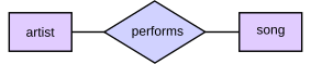
A relationship captures how two or more entities are related to one another. Relationships can be thought of as verbs, linking two or more nouns. Examples: an owns relationship between a company and a computer, a supervises relationship between an employee and a department, a performs relationship between an artist and a song, a proved relationship between a mathematician and a theorem. Relationships are represented as diamonds, connected by lines to each of the entities in the relationship.
Entities and relationships can both have attributes. Examples: an employee entity might have a Social Security Number (SSN) attribute; the proved relationship may have a date attribute. Attributes are represented as ellipses connected to their owning entity sets by a line.
Every entity (unless it is a weak entity) must have a minimal set of uniquely identifying attributes, which is called the entity's primary key.
Entity-relationship diagrams don't show single entities or single instances of relations. Rather, they show entity sets and relationship sets. Example: a particular song is an entity. The collection of all songs in a database is an entity set. The eaten relationship between a child and her lunch is a single relationship. The set of all such child-lunch relationships in a database is a relationship set.
Lines are drawn between entity sets and the relationship sets they are involved in. If all entities in an entity set must participate in the relationship set, a thick or double line is drawn. This is called a participation constraint. If each entity of the entity set can participate in at most one relationship in the relationship set, an arrow is drawn from the entity set to the relationship set. This is called a key constraint. To indicate that each entity in the entity set is involved in exactly one relationship, a thick arrow is drawn.
[edit] Alternative diagramming conventions
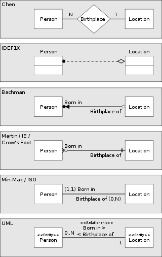

Chen's notation for entity-relationship modelling uses rectangles to represent entities, and diamonds to represent relationships. This notation is appropriate because Chen's relationships are first-class objects: they can have attributes and relationships of their own.
Alternative conventions, with partly historical meaning are:
- IDEF1X[4]
- The Bachman notation of Charles Bachman
- The Martin notation of James Martin
- The (min, max)-notation of Jean-Raymond Abrial in 1974, and
- The UML standard
- The EXPRESS
[edit] Crow's Foot
One alternative notation, known as "crow's foot" notation, was developed independently: in these diagrams, entities are represented by boxes, and relationships by labelled arcs.
The "Crow's Foot" notation represents relationships with connecting lines between entities, and pairs of symbols at the ends of those lines to represent the cardinality of the relationship. Crow's Foot notation is used in Barker's Notation and in methodologies such as SSADM and Information Engineering.
For a while Chen's notation was more popular in the United States, while Crow's Foot notation was used primarily in the UK, being used in the 1980s by the then-influential consultancy practice CACI. Many of the consultants at CACI (including Barker) subsequently moved to Oracle UK, where they developed the early versions of Oracle's CASE tools; this had the effect of introducing the notation to a wider audience, and it is now used in many tools including System Architect, Visio, PowerDesigner, Toad Data Modeler, DeZign for Databases, OmniGraffle, MySQL Workbench and Dia. Crow's foot notation has the following benefits:
- Clarity in identifying the many, or child, side of the relationship, using the crow's foot.
- Concise notation for identifying mandatory relationship, using a perpendicular bar, or an optional relation, using an open circle.
- Shows a clear and concise notation that identifies all classes
[edit] ER diagramming tools
There are many ER diagramming tools. Some of the proprietary ER diagramming tools are Avolution, ConceptDraw, ER/Studio, ERwin, DeZign for Databases, MEGA International, OmniGraffle, Oracle Designer, PowerDesigner, Rational Rose, SmartDraw, Sparx Enterprise Architect, SQLyog, Toad Data Modeler, Microsoft Visio, and Visual Paradigm. A freeware ER tool that can generate database and application layer code (webservices) is the RISE Editor.
Some free software ER diagramming tools that can interpret and generate ER models, SQL and do database analysis are StarUML, MySQL Workbench, and SchemaSpy[5]. Some free software diagram tools which can't create ER diagrams but just draw the shapes without having any knowledge of what they mean or generating SQL are Kivio, Dia. Although DIA diagrams can be translated with tedia2sql.
[edit] See also
- Associative entity
- Data model
- Data structure diagram
- Enhanced Entity-Relationship Model
- Object Role Modeling
- Three schema approach
- Unified Modeling Language
- Value range structure diagrams
[edit] References
- ^ The Entity Relationship Model - Toward A Unified View of Data
- ^ A.P.G. Brown, Modelling a Real-World System and Designing a Schema to Represent It, in Data Base Description, ed Douque and Nijssen, North-Holland, 1975, ISBN 0-7204-2833-5
- ^ Paul Beynon-Davies (2004). Database Systems. Houndmills, Basingstoke, UK: Palgrave
- ^ IDEF1X
- ^ John Currier. "SchemaSpy: Graphical Database Schema Metadata Browser". SourceForge. http://schemaspy.sourceforge.net/. Retrieved on 2009-01-22.
[edit] Further reading
- Richard Barker (1990). CASE Method: Tasks and Deliverables. Wokingham, England: Addison-Wesley.
- Paul Beynon-Davies (2004). Database Systems. Houndmills, Basingstoke, UK: Palgrave
- Peter Chen (March 1976). "The Entity-Relationship Model - Toward a Unified View of Data". ACM Transactions on Database Systems 1 (1): 9-36. doi:.
[edit] External links
| Wikimedia Commons has media related to: Entity-relationship models |
- An Entity Relationship Diagram Example. Demonstrates the crow's feet notation by way of an example.
- "Entity-Relationship Modeling: Historical Events, Future Trends, and Lessons Learned" by Peter Chen.
- "English, Chinese and ER diagrams" by Peter Chen.
- Case study: E-R diagram for Acme Fashion Supplies by Mark H. Ridley.
- Logical Data Structures (LDSs) - Getting started by Tony Drewry.
- Introduction to Data Modeling

