Digital Visual Interface
From Wikipedia, the free encyclopedia
| Digital Visual Interface (DVI) | ||
|---|---|---|
|
|
||
| Type | Digital and analog computer video connector | |
| Production history | ||
| Designer | Digital Display Working Group | |
| Designed | April 1999 | |
| Produced | 1999 to present | |
| Specifications | ||
| Hot pluggable | Yes | |
| External | Yes | |
| Video signal | Digital video stream. (Single) WUXGA 1920 × 1200 @ 60 Hz (Dual) WQXGA (2560 × 1600) @ 60 Hz Analog RGB video (-3 db at 400 MHz) |
|
| Data signal | R,G,B data + clock and display data channel | |
| Bandwidth | (Single Link) 3.96 Gbit/s (Dual Link) 7.92 Gbit/s |
|
| Max. devices | 1 | |
| Protocol | 3 × Transition Minimized Differential Signaling data + clock | |
| Pins | 29 | |
| Pin out | ||
 A female DVI-I socket from the front |
||
| Pin 1 | TMDS Data 2- | Digital red - (Link 1) |
| Pin 2 | TMDS Data 2+ | Digital red + (Link 1) |
| Pin 3 | TMDS Data 2/4 shield | |
| Pin 4 | TMDS Data 4- | Digital green - (Link 2) |
| Pin 5 | TMDS Data 4+ | Digital green + (Link 2) |
| Pin 6 | DDC clock | |
| Pin 7 | DDC data | |
| Pin 8 | Analog vertical sync | |
| Pin 9 | TMDS Data 1- | Digital green - (Link 1) |
| Pin 10 | TMDS Data 1+ | Digital green + (Link 1) |
| Pin 11 | TMDS Data 1/3 shield | |
| Pin 12 | TMDS Data 3- | Digital blue - (Link 2) |
| Pin 13 | TMDS Data 3+ | Digital blue + (Link 2) |
| Pin 14 | +5 V | Power for monitor when in standby |
| Pin 15 | Ground | Return for pin 14 and analog sync |
| Pin 16 | Hot plug detect | |
| Pin 17 | TMDS data 0- | Digital blue - (Link 1) and digital sync |
| Pin 18 | TMDS data 0+ | Digital blue + (Link 1) and digital sync |
| Pin 19 | TMDS data 0/5 shield | |
| Pin 20 | TMDS data 5- | Digital red - (Link 2) |
| Pin 21 | TMDS data 5+ | Digital red + (Link 2) |
| Pin 22 | TMDS clock shield | |
| Pin 23 | TMDS clock+ | Digital clock + (Links 1 and 2) |
| Pin 24 | TMDS clock- | Digital clock - (Links 1 and 2) |
| C1 | Analog red | |
| C2 | Analog green | |
| C3 | Analog blue | |
| C4 | Analog horizontal sync | |
| C5 | Analog ground | Return for R, G and B signals |
The Digital Visual Interface (DVI) is a video interface standard designed to maximize the visual quality of digital display devices such as flat panel LCD computer displays and digital projectors. It was developed by an industry consortium, the Digital Display Working Group (DDWG). It is designed for carrying uncompressed digital video data to a display. It is partially compatible with the High-Definition Multimedia Interface (HDMI) standard in digital mode (DVI-D), and VGA in analog mode (DVI-A).
Contents |
[edit] Overview
The DVI interface uses a digital protocol in which the desired illumination of pixels is transmitted as binary data. When the display is driven at its native resolution, it will read each number and apply that brightness to the appropriate pixel. In this way, each pixel in the output buffer of the source device corresponds directly to one pixel in the display device, whereas with an analog signal the appearance of each pixel may be affected by its adjacent pixels as well as by electrical noise and other forms of analog distortion.
Previous standards such as the analog VGA were designed for CRT-based devices and thus did not use discrete time display addressing. As the analog source transmits each horizontal line of the image, it varies its output voltage to represent the desired brightness. In a CRT device, this is used to vary the intensity of the scanning beam as it moves across the screen.
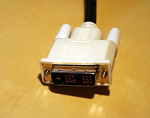
DVI cable connectors are designed in such a way as not to allow the user to connect the cable in an incorrect position or orientation. DVI connectors are available in five models, differing in the way they handle analog or digital transfers.
In the digital transfer one or two channels are present. Video and monitor cards which are exclusively digital cannot be connected to analog, but can be connected to equipment that handles both analog and digital signals. The DVI standard also supports the Display Data Channel (DDC) and the Extended Display Identification Data (EDID), which allows computers to communicate with different monitor extensions.
"DVI-I" stands for "DVI-Integrated" and supports both digital and analog transfers, so it works with both digital and analog Visual Display Units. "DVI-D" stands for "DVI-Digital" and supports digital transfers only.
Unlike HDMI, DVI usually carries no audio data (see "DVI-I" below).
[edit] Technical discussion
The data format used by DVI is based on the PanelLink serial format devised by the semiconductor manufacturer Silicon Image Inc. This uses Transition Minimized Differential Signaling (TMDS). A single DVI link consists of four twisted pairs of wires (red, green, blue, and clock) to transmit 24 bits per pixel. The timing of the signal almost exactly matches that of an analog video signal. The picture is transmitted line by line with blanking intervals between each line and each frame, and without packetization. No compression is used and there is no support for only transmitting changed parts of the image. This means that the whole frame is constantly re-transmitted. The specification (see below for link) does, however, include a paragraph on "Conversion to Selective Refresh" (under 1.2.2), suggesting this feature for future devices.
With a single DVI link, the largest resolution possible at 60 Hz is 2.75 megapixels (including blanking interval). For practical purposes, this allows a maximum screen resolution at 60 Hz of 1915 x 1436 pixels (standard 4:3 ratio), 1854 x 1483 pixels (5:4 ratio) or 2098 x 1311 (widescreen 8:5 ratio). The DVI connector therefore has provision for a second link, containing another set of red, green, and blue twisted pairs. When more bandwidth is required than is possible with a single link, the second link is enabled, and alternate pixels may be transmitted on each, allowing resolutions up to 4 megapixels at 60 Hz. The DVI specification mandates a fixed single link maximum pixel clock frequency of 165 MHz, where all display modes that require less than this must use single link mode, and all those that require more must switch to dual link mode. When both links are in use, the pixel rate on each may exceed 165 MHz. The second link can also be used when more than 24 bits per pixel is required, in which case it carries the least significant bits. The data pairs carry binary data at ten times the pixel clock reference frequency, for a maximum data rate of 1.65 Gbit/s x 3 data pairs for a single DVI link.
Like modern analog VGA connectors, the DVI connector includes pins for the display data channel (DDC). DDC2 (a newer version of DDC) allows the graphics adapter to read the monitor's extended display identification data (EDID). If a display supports both analog and digital signals in one input, each input can host a distinct EDID. If both receivers are active, analog EDID is used.
The maximum length of DVI cables is not included in the specification since it is dependent on bandwidth requirements (the resolution of the image being transmitted). In general, cable lengths up to 4.5 m (15 ft) will work for displays at resolutions of 1920 x 1200. Cable lengths up to 15 m (50 ft) can be used with displays at resolutions up to 1280 x 1024. For longer distances, the use of a DVI booster is recommended to mitigate signal degradation. DVI boosters may or may not use an external power supply.
[edit] Connector
The DVI connector usually contains pins to pass the DVI-native digital video signals. In the case of dual-link systems, additional pins are provided for the second set of data signals.
As well as digital signals, the DVI connector includes pins providing the same analog signals found on a VGA connector, allowing a VGA monitor to be connected with a simple plug adapter. This feature was included in order to make DVI universal, as it allows either type of monitor (analog or digital) to be operated from the same connector.
The DVI connector on a device is therefore given one of four names, depending on which signals it implements:
- DVI-D (digital only)
- DVI-A (analog only)
- DVI-I (integrated, digital & analog)
- M1-DA (integrated, digital, analog & USB)
The connector also includes provision for a second data link for high resolution displays, though many devices do not implement this. In those that do, the connector is sometimes referred to as DVI-DL (dual link).
The long flat pin on a DVI-I connector is wider than the same pin on a DVI-D connector, so it is not possible to connect a male DVI-I to a female DVI-D by removing the 4 analog pins. It is possible, however, to connect a male DVI-D cable to a female DVI-I connector. Many flat panel LCD monitors have only the DVI-D connection so that a DVI-D male to DVI-D male cable will suffice when connecting the monitor to a computer's DVI-I female connector.
DVI is the only widespread video standard that includes analog and digital transmission options in the same connector.[1] Competing standards are exclusively digital: these include a system using low-voltage differential signaling (LVDS), known by its proprietary names FPD (for Flat-Panel Display) Link and FLATLINK; and its successors, the LVDS Display Interface (LDI) and OpenLDI.
Some new DVD players, TV sets (including HDTV sets) and video projectors have DVI/HDCP connectors; these are physically the same as DVI connectors but transmit an encrypted signal using the HDCP protocol for copy protection. Computers with DVI video connectors can use many DVI-equipped HDTV sets as a display; however, due to Digital Rights Management, it is not clear whether such systems will eventually be able to play protected content, as the link is not encrypted.
USB signals are not incorporated into the connector, but were earlier incorporated into the VESA Plug and Display connector used by InFocus on their projector systems, and in the Apple Display Connector, which was used by Apple Computer until 2005.
The DMS-59 connector is a way to combine two analog and two digital signals in one plug. It is commonly used when a single graphics card has two outputs.
M1-DA connectors are sometimes labeled as DVI-M1; they are used for the VESA Enhanced Video Connector and VESA Plug and Display schemes.
[edit] Specifications
[edit] Digital
- Minimum clock frequency: 25.175 MHz
- Maximum clock frequency in single link mode: Capped at 165 MHz (up to 3.96 Gbit/s)
- Maximum clock frequency in dual link mode: Limited only by cable quality (up to 7.92 Gbit/s)
- Pixels per clock cycle: 1 (single link) or 2 (dual link)
- Bits per pixel: 24 (single and dual link) or 48 (dual link only)
- Example display modes (single link):
- HDTV (1920 × 1080) @ 60 Hz with CVT-RB blanking (139 MHz)
- UXGA (1600 × 1200) @ 60 Hz with GTF blanking (161 MHz)
- WUXGA (1920 × 1200) @ 60 Hz with CVT-RB blanking (154 MHz)
- SXGA (1280 × 1024) @ 85 Hz with GTF blanking (159 MHz)
- WXGA+ (1440 x 900) @ 60 Hz (107 MHz)
- WQUXGA (3840 × 2400) @ 17 Hz (164 MHz)
- Example display modes (dual link):
- QXGA (2048 × 1536) @ 75 Hz with GTF blanking (2 × 170 MHz)
- HDTV (1920 × 1080) @ 85 Hz with GTF blanking (2 × 126 MHz)
- WQXGA (2560 × 1600) @ 60 Hz with GTF blanking (2 × 174 MHz) (30-inch (762 mm) Apple, Dell, Gateway, HP, NEC, Quinux, and Samsung LCDs)
- WQXGA (2560 × 1600) @ 60 Hz with CVT-RB blanking (2 × 135 MHz) (30-inch (762 mm) Apple, Dell, Gateway, HP, NEC, Quinux, and Samsung LCDs)
- WQUXGA (3840 × 2400) @ 33 Hz with GTF blanking (2 × 159 MHz)
GTF (Generalized Timing Formula) is a VESA standard which can easily be calculated with the Linux gtf utility.
CVT-RB (Coordinated Video Timing-Reduced Blanking) is a VESA standard which offers reduced horizontal and vertical blanking for non-CRT based displays.[2]
[edit] Clock and data relationship
The DVI data channel operates at a bit-rate multiple of 10 times the frequency of the clock signal. In other words, for every DVI clock there are 10 bits provided on each of the three data channels. The data is encoded using a standard 8b/10b encoding to provide a minimum transition density in which there are no more than five consecutive bits of the same value, which is necessary to provide reference edges for clock/data recovery circuits. As indicated in version 1.0 of the specification, the clock rate is the same as the pixel rate plus framing overhead, while there are usually 24 bits per pixel. For example, a (640 × 480) @ 60 Hz display has a pixel rate of 18.4 MHz (plus blanking overhead) so this is the minimum needed clock. But the data is actually (640 × 480) @ 60 Hz × 24 bits per pixel which is 442 Mbit/s, or 147 Mbit/s per channel. Include TMDS overhead and you need a 184 Mbit/s data stream on each of the three data channels.
Since the data is switching at 10 times the clock rate, a receiver must recover the faster bit clock from the data lines itself (using a PLL or DLL, for instance) in a process known as clock/data recovery. The DVI clock is effectively a 1/10th frequency reference clock that is useful for the clock/data recovery circuitry to synchronize to the bitstream. DVI provides a reference clock while other serial data interfaces such as PCI Express and SATA do not because the bit rate carried by the DVI interface may vary across a wide frequency range depending on the video format being rendered. Serial interfaces that do not explicitly carry the reference clock are typically defined to run at a specific known frequency or several derivative frequencies that are related by whole number multiples (for example 2.5 Gbit/s and 5.0 Gbit/s for successive generations of PCI Express and 1.5 Gbit/s and 3.0 Gbit/s for successive generations of SATA), so in these cases a fixed frequency reference clock can be generated locally at the receiver that performs the clock/data recovery.
[edit] Analog
- RGB bandwidth: 400 MHz at -3 dB
[edit] Proposed successors
IEEE 1394 is proposed by High Definition Audio-Video Network Alliance (HANA Alliance) for all cabling needs, including video, over CoAx and/or 1394 cable as a combined data stream.
High-Definition Multimedia Interface (HDMI), a forward-compatible standard, that also includes digital audio transmission.
Unified Display Interface (UDI) was proposed by Intel to replace both DVI and HDMI, but was deprecated in favor of DisplayPort.
DisplayPort is a license-free standard proposed by VESA to succeed DVI, which also has DRM capabilities.
[edit] References
- DDWG promoters (1999-04-02) (pdf). Digital Visual Interface. Revision 1.0: Initial Specification Release. Digital Display Working Group. http://www.ddwg.org/lib/dvi_10.pdf.
- ^ Kruegle, Herman. "8". CCTV Surveillance: Analog and Digital Video Practices And Technology. Butterworth-Heinemann. pp. 268. ISBN 0750677686.
- ^ "Advanced Timing and CEA/EIA-861B Timings". NVIDIA. http://www.nvidia.com/object/advanced_timings.html.
|
||||||||||||||||||||
|
|||||||||||||||||||||||
|
||||||||||||||||||||||||||

