D-subminiature
From Wikipedia, the free encyclopedia

The D-subminiature or D-sub is a common type of electrical connector used particularly in computers. Calling them "subminiature" was appropriate when they were first introduced, but today they are among the largest common connectors used in computers.
Contents |
[edit] Description and nomenclature

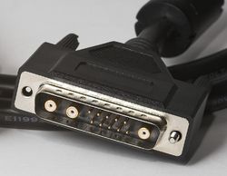
A D-sub contains two or more parallel rows of pins or sockets usually surrounded by a D-shaped metal shield that provides mechanical support, some screening against electromagnetic interference, and ensures correct orientation. The part containing pin contacts is called the male connector or plug, while that containing socket contacts is called the female connector or socket. The socket's shield fits tightly inside the plug's shield. The shields are connected to the overall screens of the cables (when screened cables are used), creating an electrically continuous screen covering the whole cable and connector system.
D-subminiature connectors were invented by ITT Cannon, part of ITT Corporation, in 1952.[1] Cannon's part-numbering system uses a D as the prefix for the whole series, followed by a letter denoting the shell size (A=15 pin, B=25 pin, C=37 pin, D=50 pin, E=9 pin), followed by the actual number of pins, followed by the gender (P=plug, S=socket). [2] For example, DB25 denotes a D-sub with a 25 position shell size and a 25 position contact configuration. The contacts in these connectors are spaced approximately 0.108 inches (2.74 mm) apart with the rows spaced 0.112 inches (2.84 mm) apart.
Cannon also produced D-subs with larger positions in place of some of the normal pin positions that could be used for either high-current, high-voltage, or co-axial inserts. The DB13W3 variant was commonly used for high-performance video connections; this variant provided 10 regular (#20) pins plus three coaxial contacts for the red, green, and blue video signals.
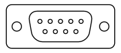
In the photograph below, the connector on the left is a 9-pin (DE-9) connector plug, and the one on the right is a 25-pin (DB25) socket. The hexagonal pillars at either end of each connector have a threaded stud (not visible) that passes through flanges on the connector, fastening it to the metal panel. They also have a threaded hole that receives the jackscrews on the cable shell, to hold the plug and socket together.
Possibly because the original PC used DB25 connectors for the serial and parallel ports, many people,[who?] not knowing the significance of the letter "B" as the shell size, began to call all D-sub connectors "DB" connectors instead of specifying "DA," "DC" or "DE." When the PC serial port began to use 9-pin connectors, they were often called "DB9" instead of DE9. It is now common to see DE9 connectors sold as "DB9" connectors. DB-9 is nearly always intended to be a 9 pin connector with an E size shell.
There are now D-sub connectors which have the original shell sizes, but more pins, and the names follow the same pattern. For example, the DE15, usually found in VGA cables, has 15 pins, in three rows, in an E size shell. The full list of connectors with this pin spacing is: DE15, DA26, DB44, DC62, and DD78. Alternatively, following the same confusion mentioned above in which all D-sub connectors are called "DB", these connectors are often called DB15HD, DB26HD, DB44HD, DB62HD, and DB78HD, where the "HD" stands for "high density". They all have 3 rows of pins, except the DD78, which has 4.
A series of D-sub connectors with even denser pins is called "double density", and consists of DE19, DA31, DB52, DC79, and DD100. They have 4 rows of pins.
There is yet another similar family of connectors that is easy to confuse with the D-sub family, but is not part of it. These connectors have names like "HD50" and "HD68", and have a D-shaped shell but the shell is about half the width of a DB25. They are common in SCSI attachments.
The suffixes M and F (male and female) are sometimes used instead of the original P and S (plug and socket).
The original D-subminiature connectors are now defined by an international standard, DIN 41652. The United States military also specifies D-subminiature connectors using the MIL-DTL-24308 standard.[3]
[edit] Typical applications

Left: DE9M Right: DB25F.
The widest application of D-subs is for RS-232 serial communications, though the standard did not make this connector mandatory. RS-232 devices originally used the DB25 25-pin D-sub, but for many applications the less common signals were omitted, allowing a DE9 9-pin D-sub to be used. Originally, the use of female connectors at the device and male connectors at the cable was almost ubiquitous, but IBM reversed this arrangement in their PC line beginning in the early 1980s to prevent a mix-up of RS-232 ports with parallel printer ports. Since then, computers tend to have male connectors at the device, while modems usually still have female connectors.
On PCs, 9-pin and 25-pin plugs are used for the RS-232 (serial) ports and 25-pin sockets are used for the (parallel) printer ports (instead of the Centronics socket found on the printer itself). 25-pin sockets on Macintosh computers are typically SCSI connectors (again in contrast to the Centronics C50 connector typically found on the peripheral).
A male DE9 connector on the back of an IBM-PC-compatible computer is typically a serial port connector. IBM introduced the DE9 connector for RS-232 on PCs with the Personal Computer AT in 1984. A female 9-pin connector on the same computer may be a video display output: monochrome, CGA, or EGA. Even though these all use the same connector, the displays cannot all be interchanged and monitors or video interfaces may even be damaged if connected to an incompatible device using the same connector. Later analog video (VGA and later) adapters replaced these connectors by DE15 15-pin high-density sockets, which have three rows of five contacts each in the space that was previously occupied by two rows of contacts, five in the top row and four in the bottom row. Other common names for DE15 connectors are HD15, where HD stands for High Density, and (less accurately) DB15 and DB15HD.
From the late 1970s and all through the '80s, DE9s without the pair of fastening screws were used as game controller connectors in a variety of video game consoles and home computers, quite possibly due to the success of the revolutionary Atari 2600 game console that used them. Computer systems using them included the Atari 8-bit and ST lines; the Commodore VIC-20, 64, 128, and Amiga; the Amstrad; the SEGA Master System and Genesis. The Sinclair ZX Spectrum, which did not have a built in joystick connector of any kind, was commonly used with adapters for DE9 joysticks. They were not used in the Apple and PC systems, nor in most newer game consoles. Wired in the standard way, they supported one digital (3 positions x 2 axes, 1 button) joystick or one pair of analog paddles; on many systems a computer mouse or a light pen was also supported through these sockets, however these mice were not usually interchangeable between different systems.
DA15S connectors are used for PC joystick connectors, where each DA15 connector supports two joysticks each with two analog axes and two buttons. In other words, one DA15S "game adapter" connector has 4 analog potentiometer inputs and 4 digital switch inputs. This interface is strictly input-only, though it does provide +5V DC power. Some joysticks with more than two axes and/or more than two buttons use the signals designated for both joysticks. Conversely, Y-adapter cables are available that allow two separate joysticks to be connected to a single DA15 game adapter port; if a joystick connected to one of these Y-adapters has more than two axes or buttons, only the first two of each will work. The IBM DA15 PC game connector has been modified to add a (usually MPU-401 compatible) MIDI interface, and this is often implemented in the game connectors on third-party sound cards, particularly the Sound Blaster line from Creative Labs. The "standard" straight game adapter connector (introduced by IBM) has three ground pins and four +5V power pins, and the MIDI adaptation replaces one of the grounds and one of the +5V pins, both on the bottom row of pins, with MIDI In and MIDI Out signal pins. (There is no MIDI Thru provided.) Creative Labs introduced this adaptation.fact-check this (last sentence)
DE9 connectors are also used for some token ring and other computer networks. The DA15S was also used for the AUI connectors included on Ethernet cards in the 1980s and 1990s, albeit with a sliding latch to lock the connectors together instead of the usual hex studs with threaded holes. (The sliding latch was intended to be quicker to engage and disengage and to work in places where jack-screws could not be used for reasons of component shape.
Many uninterruptible power supply units have a DE9F connector on them, in order to signal to the attached computer via an RS-232 interface. Often these do not send data serially to the computer but instead use the handshaking control lines to indicate low battery, power failure or other conditions. Such usage is not standardized between manufacturers and may require special cables to be supplied.

The complete range of D-sub connectors also includes 15-pin DA15s (two rows of 7 and 8); 37-pin DC37s (two rows of 18 and 19); and 50-pin DD50s (two rows of 17 and one of 16), the last two being used in industrial products. The 15-pin DA15 has been notably used for color video output on early Macintosh computers, and for the IBM-defined PC analog joystick connector as noted above. Finally, the early Macintosh and Apple II line of computers used a very rare 19 pin D-sub for connecting to external floppy disk drives, and the Commodore Amiga used an unusual 23-pin version for both its video output and for connecting an external floppy disk drive.

TASCAM used DB25 connectors for their multi-track recording audio equipment (TDIF), and Logitek Audio later did the same for its broadcast consoles, though with different pinouts. [1] A few patch panels have been made which have the DB25 connectors on the back with phone jacks (or even TRS jacks) on the front, however these are normally wired for TASCAM, which is more common outside of broadcasting.
In broadcast and professional video, "parallel digital" is a digital video interface that utilizes DB25 connectors, per the SMPTE 274M specification adopted in the late 1990s. The more common SMPTE 259M "serial digital interface" (SDI) utilizes BNC connectors for digital video signal transfer.
[edit] Types and variants
D-sub connectors exist in at least five types, differentiated by the method used to attach wires to the contacts. These are solder-cup or solder-bucket, insulation displacement, crimp, PCB pins, and wire wrap.
- Solder-bucket contacts have a cavity into which the stripped wire is inserted and hand-soldered (a somewhat tricky process especially to do alone as the wire can easily pop out of the bucket whilst soldering unless held there).
- Insulation displacement contacts (IDC) allow a ribbon cable to be forced onto sharp tines on the back of the contacts; this action pierces the insulation of all the wires simultaneously. This is a very quick means of assembly whether done by hand or automatically but requires use of flat ribbon cable which can be awkward to handle and makes it difficult to make cables with different connections at each end.
- Crimp contacts are assembled by inserting a stripped wire end into a cavity in the rear of the contact, then crushing the cavity using a crimp tool causing it to grip the wire tightly at many points. The crimped contact is then inserted into the connector where it locks into place. Individual crimped pins can be removed later with a tool inserted into the rear of the connector. This "rear release" feature is valuable when pins are damaged or modifications must be made to the circuits.
- PCB pins as the name suggests are intended to be soldered directly to a printed circuit board and not to a wire. These connectors are frequently mounted at a right-angle to the PCB allowing a cable to be plugged into the edge of the PCB assembly. Blocks containing multiple stacked D connectors (and sometimes other connectors too) are nearly always seen on ATX (or variants thereof) PC motherboards but aren't generally seen elsewhere.
- Wire wrap connections are made by wrapping solid wire around a square post with a wire wrap tool. This type of connection is usually used in prototyping.
A smaller type of connector derived from the D-subminiature, and about half the linear size, is called the microminiature D, or micro-D, which is a trademark of ITT Cannon. This connector is used in industrial instrumentation products. A few manufacturers make nano-D connectors, which are about half the size again.
[edit] Usage
The 25 pin D-sub connector has become the standard in the recording studio industry for multi-channel analog audio and AES Digital audio.
The D-sub connector family is now in decline for general usage in the computer industry, due to size and cost. For portable devices such as PDAs, MP3 players or mobile phones, the D-sub connector is usually too large to fit. In the laptop computer sector, where weight and size are crucial, many models no longer include D-subs. Even small form factor desktop PCs may find D-sub connectors too large for their value.
Because of the relatively complex shapes and assembly, especially the shaped metal D shield, and screws and nuts for physical securing, D-sub connectors are now quite expensive compared to other common connectors, which are mostly simpler. In the retail PC world where margins are very thin, these connectors are a natural target for removal.
The physical design is not friendly to consumer plug-and-play applications. Thin metal pins, especially in higher-density connectors, are easily bent or broken, especially when frequently plugged in "blind" behind equipment. Although ESD and EMI resistant D-sub connectors exist, the fundamental design was never intended to protect from electrostatic discharge or electromagnetic interference or facilitate very high frequency interconnections.[citation needed]
For video purposes, the DE15HD connector is in the process of being replaced by digital DVI and HDMI connectors, although this transition is proceeding more slowly than in the other areas, since many analog CRT monitors are still in use and the analog version of the DVI connector, while existing, is not particularly useful for those, since it is similar in price and even higher in complexity compared to the D-sub line.
For the majority of other consumer applications, D-sub serial and parallel connectors have been replaced by the physically much simpler and cheaper IEEE 1394 (FireWire), SATA, USB or Ethernet connectors.
[edit] See also
[edit] Notes and references
- ^ Are D Subs from all manufactures compatible? — reply in the FAQ section of the Cannon company web
- ^ ITT Cannon 90° PCB Selection Guide, accessed at RS Components website on 2007-09-10
- ^ http://www.dscc.dla.mil/Programs/MilSpec/ListDocs.asp?BasicDoc=MIL-DTL-24308
[edit] External links
- Ishmael Stefanov-Wagner's web page on D-Subminiature Nomenclature
- A list of common computer connectors, including most D-sub
- Devices with DE-9 connectors
|
||||||||||||||||||||
|
|||||||||||||||||||||||

