Coaxial cable
From Wikipedia, the free encyclopedia

Coaxial cable, or coax, is a cable with an inner conductor surrounded by a tubular insulating layer typically of a flexible material with a high dielectric constant, all of which are surrounded by a conductive layer (typically of fine woven wire for flexibility, or of a thin metallic foil), and finally covered with a thin insulating layer on the outside. The term coaxial comes from the inner conductor and the outer shield sharing the same geometric axis. Coaxial cable is used as a transmission line for radio frequency signals, in applications such as connecting radio transmitters and receivers with their antennas, computer network (Internet) connections, and distributing cable television signals. One advantage of coax over other types of transmission line is that in an ideal coaxial cable the electromagnetic field carrying the signal exists only in the space between the inner and outer conductors. This allows coaxial cable runs to be installed next to metal objects such as gutters without the power losses that occur in other transmission lines, and provides protection of the signal from external electromagnetic interference.
Coaxial cable should not be confused with other shielded cable used for carrying lower frequency signals such as audio signals. Shielded cable is similar in that it consists of a central wire or wires surrounded by a tubular shield conductor, but it is not constructed with the precise conductor spacing needed to function efficiently as a radio frequency transmission line.
Contents |
[edit] How it works
Like an electrical power cord, coaxial cable conducts AC electric current between locations. Like these other cables, it has two conductors, the central wire and the tubular shield. At any moment the current is traveling outward in one of the conductors, and returning in the other. However, since it is alternating current, the current reverses direction many times a second. Coaxial cable differs from other cable because it is designed to carry radio frequency current. This has a frequency much higher than the 50 or 60 Hz used in mains (electric power) cables, reversing direction millions to billions of times per second. Like other types of radio transmission line, this requires special construction to prevent power losses:
- If an ordinary wire is used to carry high frequency currents, the wire acts as an antenna, and the high frequency currents radiate off the wire as radio waves, causing power losses. To prevent this, in coaxial cable one of the conductors is formed into a tube and encloses the other conductor. This confines the radio waves from the central conductor to the space inside the tube. To prevent the outer conductor, or shield, from radiating, it is connected to electrical ground, keeping it at a constant potential.
- The dimensions and spacing of the conductors are uniform. Any abrupt change in the spacing of the two conductors along the cable tends to reflect radio frequency power back toward the source, causing a condition called standing waves. This acts as a bottleneck, reducing the amount and quality of the transmitted power. To hold the shield at a uniform distance from the central conductor, the space between the two is filled with a plastic dielectric. Manufacturers specify a minimum bend radius, to prevent kinks that would cause reflections. The connectors used with coax hold the correct spacing through the body of the connector.
[edit] Description
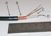
A: outer plastic sheath
B: copper screen
C: inner dielectric insulator
D: copper core
Coaxial cable design choices affect physical size, frequency performance, attenuation, power handling capabilities, flexibility, strength and cost. The inner conductor might be solid or stranded; stranded is more flexible. To get better high-frequency performance, the inner conductor may be silver plated. Sometimes copper-plated iron wire is used as an inner conductor.
The insulator surrounding the inner conductor may be solid plastic, a foam plastic, or may be air with spacers supporting the inner wire. The properties of dielectric control some electrical properties of the cable. A common choice is a solid polyethylene (PE) insulator, used in lower-loss cables. Solid Teflon (PTFE) is also used as an insulator. Some coaxial lines use air (or some other gas) and have spacers to keep the inner conductor from touching the shield.
There is variety in the shield. Conventional coaxial cable has braided copper wire forming the shield. This allows the cable to be flexible, but it also means there are gaps in the shield layer, and the inner dimension of the shield varies slightly because the braid cannot be flat. Sometimes the braid is silver plated. For better shield performance, some cables have a double-layer shield. The shield might be just two braids, but it is more common now to have a thin foil shield covered by a wire braid. Some cables may invest in more than two shield layers. Other shield designs sacrifice flexibility for better performance; some shields are a solid metal tube. Those cables cannot take sharp bends, as the shield will kink, causing losses in the cable. Many Cable television (CATV) distribution systems use such "hard line" cables, as they provide a lower signal loss.
The insulating jacket can be made from many materials. A common choice is PVC, but some applications may require fire-resistant materials. Outdoor applications may require the jacket to resist ultraviolet light and oxidation. For internal chassis connections the insulating jacket may be omitted.
Connections at the ends of coaxial cables are usually made with RF connectors.
[edit] Signal propagation
Open wire transmission lines have the property that the electromagnetic wave propagating down the line extends into the space surrounding the parallel wires. These lines have low loss, but also have undesirable characteristics. They cannot be bent, twisted or otherwise shaped without changing their characteristic impedance, causing reflection of the signal back toward the source. They also cannot be run along or attached to anything conductive, as the extended fields will induce currents in the nearby conductors causing unwanted radiation and detuning of the line. Coaxial lines solve this problem by confining the electromagnetic wave to the area inside the cable, between the center conductor and the shield. The transmission of energy in the line occurs totally through the dielectric inside the cable between the conductors. Coaxial lines can therefore be bent and moderately twisted without negative effects, and they can be strapped to conductive supports without inducing unwanted currents in them. In radio-frequency applications up to a few gigahertz, the wave propagates only in the transverse electric magnetic (TEM) mode, which means that the electric and magnetic fields are both perpendicular to the direction of propagation. However, above a certain cutoff frequency, transverse electric (TE) and/or transverse magnetic (TM) modes can also propagate, as they do in a waveguide. It is usually undesirable to transmit signals above the cutoff frequency, since it may cause multiple modes with different phase velocities to propagate, interfering with each other. The outer diameter is roughly inversely proportional to the cutoff frequency.
The outer conductor can also be made of (in order of decreasing leakage and in this case degree of balance): double shield, wound foil, woven tape, braid. The ohmic losses in the conductor increase in this order: Ideal conductor (no loss), superconductor, silver, copper. It is further increased by rough surface (in the order of the skin depth, lateral: current hot spots, longitudinal: long current path) for example due to woven braid, multistranded conductors or a corrugated tube as a conductor) and impurities especially oxygen in the metal (due to a lack of a protective coating). Litz wire is used between 1 kHz and 1 MHz to reduce ohmic losses. Coaxial cables require an internal structure of an insulating (dielectric) material to maintain the spacing between the center conductor and shield. The dielectric losses increase in this order: Ideal dielectric (no loss), vacuum, air, Polytetrafluoroethylene (PTFE), polyethylene foam, and solid polyethylene. It is further increased by impurities like water. In typical applications the loss in polyethylene is comparable to the ohmic loss at 1 GHz and the loss in PTFE is comparable to ohmic losses at 10 GHz. A low dielectric constant allows for a greater center conductor: less ohmic losses. An inhomogeneous dielectric needs to be compensated by a noncircular conductor to avoid current hot-spots.
[edit] Connectors

From the signal point of view, a connector can be viewed as a short, rigid cable. The connector usually has the same impedance as the related cable and probably has a similar cutoff frequency although its dielectric may be different. Some connectors are gold or rhodium plated, while some connectors use nickel or tin plating. Silver is also used due to its excellent conductivity. Although silver oxidizes quickly, the silver oxide that is produced is still conductive. This may pose a cosmetic issue, but it does not degrade performance.
One increasing development has been the wider adoption of micro-miniature coaxial cable in the consumer electronics sector in recent years. Wire and cable companies such as Tyco, Sumitomo Electric, Hitachi Cable, Fujikura and LS Cable all manufacture these cables, which can be used in mobile phones.
[edit] Important parameters
Coaxial cable is a particular kind of transmission line, so the circuit models developed for general transmission lines are appropriate. See Telegrapher's equation.
[edit] Physical parameters
- Outside diameter of inner conductor, d.
- Inside diameter of shield, D.
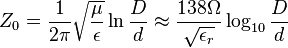
- Dielectric constant of the insulator, ε. The dielectric constant is often quoted as the relative dielectric constant εr referred to the dielectric constant of free space ε0: ε = εrε0. When the insulator is a mixture of different dielectric materials (e.g., polyethylene foam is a mixture of polyethylene and air), then the term effective dielectric constant εeff is often used.
- Magnetic permeability of the insulator. μ Permeability is often quoted as the relative permeability μr referred to the permeability of free space μ0: μ = μrμ0. The relative permeability will almost always be 1.
[edit] Fundamental electrical parameters
- Shunt Capacitance per unit length, in farads per metre.

- Series Inductance per unit length, in Henrys per metre.

- Series Resistance per unit length, in ohms per metre. The resistance per unit length is just the resistance of inner conductor and the shield at low frequencies. At higher frequencies, skin effect increases the effective resistance by confining the conduction to a thin layer of each conductor.
- Shunt Conductance per unit length, in mhos per metre. The shunt conductance is usually very small because insulators with good dielectric properties are used (a very low loss tangent). At high frequencies, a dielectric can have a significant resistive loss.
[edit] Derived electrical parameters
- Characteristic impedance in ohms (Ω). Neglecting resistance per unit length and conductance per unit length for most coaxial cables, the characteristic impedance is determined from the capacitance per unit length (C) and the inductance per unit length (L). The simplified expression is (
 ). Those parameters are determined from the ratio of the inner (d) and outer (D) diameters and the dielectric constant (ε). The characteristic impedance is given by[1]
-
- Assuming the dielectric properties of the material inside the cable do not vary appreciably over the operating range of the cable, this impedance is frequency independent above about five times the shield cutoff frequency. For typical coaxial cables, the shield cutoff frequency is 600 (RG-6A) to 2,000 Hz (RG-58C).[2]
- Attenuation (loss) per unit length, in decibels per metre. This is dependent on the loss in the dielectric material filling the cable, and resistive losses in the center conductor and outer shield. These losses are frequency dependent, the losses becoming higher as the frequency increases. Skin effect losses in the conductors can be reduced by increasing the diameter of the cable. A cable with twice the diameter will have half the skin effect resistance. Ignoring dielectric and other losses, the larger cable would halve the dB/meter loss. In designing a system, engineers consider not only the loss in the cable, but also the loss in the connectors.
- Velocity of propagation, in meters per second. The velocity of propagation depends on the dielectric constant and permeability (which is usually 1).

- Cutoff frequency is determined by the possibility of exciting other propagation modes in the coaxial cable. The average circumference of the insulator is π(D + d) / 2. Make that length equal to 1 wavelength in the dielectric. The TE01 cutoff frequency is therefore
-
 .
.
- Peak Voltage
- Outside diameter, which dictates which connectors must be used to terminate the cable.
[edit] Significance of impedance
The best coaxial cable impedances in high-power, high-voltage, and low-attenuation applications were experimentally determined in 1929 at Bell Laboratories to be 30, 60, and 77 Ω respectively. For an air dielectric coaxial cable with a diameter of 10mm the attenuation is lowest at 77 ohms when calculated for 10 GHz.[1] The curve showing the power handling maxima at 30 ohms can be found here:[2]
CATV systems were one of the first applications for very large quantities of coaxial cable. CATV is typically using such low levels of RF power that power handling and high voltage breakdown characteristics were totally unimportant when compared to attenuation. Moreover, many CATV headends used 300 ohm folded dipole antennas to receive off the air TV signals. 75 ohm coax made a nice 4:1 balun transformer for these antennas as well as presented a nice attenuation specification. But this is a bit of a red herring,when normal dielectrics are added to the equation the best loss impedance drops down to values between 64 and 52 ohms. Details and a graph showing this effect can be found here: [3][citation needed] 30 Ω cable is more difficult to manufacture due to the much larger center conductor and the stiffness and weight it adds.
The arithmetic mean between 30 ohms and 77 ohms is 53.5, the geometric mean is 48 ohms. The selection of 50 ohms as a compromise between power handling capability and attenuation is generally cited as the reason for the number.
One reference to a paper presented by Bird Electronic Corp as to why 50 ohms was chosen can be found here: [4]
50 Ohms works out well for other reasons such as it corresponds very closely to the drive impedance of a half wave dipole antenna in real environments, and provides an acceptable match to the drive impedance of quarter wave monopoles as well. 73 Ω is an exact match for a centre fed dipole aerial/antenna in free space (approximated by very high dipoles without ground reflections).
RG-62 is a 93 ohm coaxial cable. It is purported that RG-62 cable was originally used in mainframe computer networks. (1970's / early 1980's). It was the cable used to connect the terminals to the terminal cluster controllers. Later some manufacturers of LAN equipment such as ARCNET adopted RG-62 as a standard. It has the lowest capacitance per unit length when compared to other coaxial cables of similar size. Capacitance is the enemy of square wave data transmission and is much more important than power handling or attenuation specifications in these environments.
All of the components of a coaxial system should have the same impedance to reduce internal reflections at connections between components. Such reflections increase signal loss and can result in the reflected signal reaching a receiver with a slight delay from the original. In analog video or TV systems this visual effect is commonly referred to as ghosting. (see Impedance matching)
[edit] Issues
[edit] Signal leakage
Signal leakage is the passage of electromagnetic fields through the shield of a cable and occurs in both directions. Ingress is the passage of an outside signal into the cable and can result in noise and disruption of the desired signal. Egress is the passage of signal intended to remain within the cable into the outside world and can result in a weaker signal at the end of the cable and radio frequency interference to near by devices.
For example, in the United States, signal leakage from cable television systems is regulated by the FCC, since cable signals use the same frequencies as aeronautical and radionavigation bands. CATV operators may also choose to monitor their networks for leakage to prevent ingress. Outside signals entering the cable can cause unwanted noise and picture ghosting. Excessive noise can overwhelm the signal, making it useless.
An ideal shield would be a perfect conductor with no holes, gaps or bumps connected to a perfect ground. However, a smooth solid copper shield would be heavy, inflexible, and expensive. Practical cables must make compromises between shield efficacy, flexibility and cost, such as the corrugated surface of hardline, flexible braid, or foil shields. Since the shields are not perfect conductors, electric fields can exist inside the shield, thus allowing radiating electromagnetic fields to go through the shield.
Consider the skin effect. The magnitude of an alternating current in an imperfect conductor decays exponentially with distance beneath the surface, with the depth of penetration being proportional to the square root of the resistivity. This means that in a shield of finite thickness, some small amount of current will still be flowing on the opposite surface of the conductor. With a perfect conductor (i.e., zero resistivity), all of the current would flow at the surface, with no penetration into and through the conductor. Real cables have a shield made of an imperfect, although usually very good, conductor, so there will always be some leakage.
The gaps or holes, allow some of the electromagnetic field to penetrate to the other side. For example, braided shields have many small gaps. The gaps are smaller when using a foil (solid metal) shield, but there is still a seam running the length of the cable. Foil becomes increasingly rigid with increasing thickness, so a thin foil layer is often surrounded by a layer of braided metal, which offers greater flexibility for a given cross-section.
This type of leakage can also occur at locations of poor contact between connectors at either end of the cable.
[edit] Ground loops
A continuous current flow, even if small, along the imperfect shield of a coaxial cable can cause visible or audible interference. In CATV systems distributing analog signals the potential difference between the coaxial network and the electrical grounding system of a house can cause a visible "hum bar" in the picture. This appears as a wide horizontal distortion bar in the picture that scrolls slowly upward. Such differences in potential can be reduced by proper bonding to a common ground at the house. See ground loop.
[edit] Induction
External current sources like switched-mode power supplies create a voltage across the inductance of the outer conductor between sender and receiver. The effect is less when there are several parallel cables, as this reduces the inductance and therefore the voltage. Because the outer conductor carries the reference potential for the signal on the inner conductor, the receiving circuit measures the wrong voltage.
[edit] Transformer effect
The transformer effect is sometimes used to mitigate the effect of currents induced in the shield. The inner and outer conductors form the primary and secondary winding of the transformer, and the effect is enhanced in some high quality cables that have an outer layer of mu-metal. Because of this 1:1 transformer, the aforementioned voltage across the outer conductor is transformed onto the inner conductor so that the two voltages can be cancelled by the receiver. Many sender and receivers have means to reduce the leakage even further. They increase the transformer effect by passing the whole cable through a ferrite core sometimes several times.
[edit] Common mode current and radiation
Common mode current occurs when stray currents in the shield flow in the same direction as the current in the center conductor, causing the coax to radiate.
Most of the shield effect in coax results from opposing currents in the center conductor and shield creating opposite magnetic fields that cancel, and thus do not radiate. The same effect helps ladder line. However, ladder line is extremely sensitive to surrounding metal objects which can enter the fields before they completely cancel. Coax does not have this problem since the field is enclosed in the shield. However, it is still possible for a field to form between the shield and other connected objects, such as the antenna the coax feeds. The current formed by the field between the antenna and the coax shield would flow in the same direction as the current in the center conductor, and thus not be canceled, and would actually cause energy to radiate from the coax itself, making it appear to be part of the antenna, affecting the radiation pattern of the antenna and possibly introducing dangerous radio frequency energy into areas near people, with the risk of radiation burns if the coax is being used for sufficiently high power transmissions. A properly placed and sized balun can prevent common mode radiation in coax.
[edit] Miscellaneous
Some senders and receivers use only a limited range of frequencies and block all others by means of an isolating transformer. Such a transformer breaks the shield for high frequencies. Still others avoid the transformer effect altogether by using two capacitors. If the capacitor for the outer conductor is implemented as one thin gap in the shield, no leakage at high frequencies occurs. At high frequencies, beyond the limits of coaxial cables, it becomes more efficient to use other types of transmission line such as wave guides or optical fiber, which offer low leakage (and much lower losses) around 200 THz and good isolation for all other frequencies.
[edit] Standards
Most coaxial cables have a characteristic impedance of either 50, 52, 75, or 93 Ω. The RF industry uses standard type-names for coaxial cables. Thanks to television, RG-6 is the most commonly-used coaxial cable for home use, and the majority of connections outside Europe are by F connectors.
A series of standard types of coaxial cable were specified for military uses, in the form "RG-#" or "RG-#/U". They date from WW II and were listed in MIL-HDBK-216 published in 1962. These designations are now obsolete. The current military standard is MIL-SPEC MIL-C-17. MIL-C-17 numbers, such as "M17/75-RG214," are given for military cables and manufacturer's catalog numbers for civilian applications. However, the RG-series designations were so common for generations that they are still used, although critical users should be aware that since the handbook is withdrawn there is no standard to guarantee the electrical and physical characteristics of a cable described as "RG-# type". The RG designators are mostly used to identify compatible connectors that fit the inner conductor, dielectric, and jacket dimensions of the old RG-series cables.
| type | approx. impedance [ohms] |
core | dielectric | overall diameter | braid | velocity factor | comments | |||
|---|---|---|---|---|---|---|---|---|---|---|
| type | [in] | [mm] | in | mm | ||||||
| RG-6/U | 75 | 1.0 mm | Solid PE | 0.185 | 4.7 | 0.270 | 8.4 | double | 0.75 | Low loss at high frequency for cable television, satellite television and cable modems |
| RG-6/UQ | 75 | Solid PE | 0.298 | 7.62 | quad | This is "quad shield RG-6". It has four layers of shielding; regular RG-6 only has one or two | ||||
| RG-8/U | 50 | 2.17 mm | Solid PE | 0.285 | 7.2 | 0.405 | 10.3 | Amateur radio; Thicknet (10BASE5) is similar | ||
| RG-9/U | 51 | Solid PE | 0.420 | 10.7 | ||||||
| RG-11/U | 75 | 1.63 mm | Solid PE | 0.285 | 7.2 | 0.412 | 10.5 | 0.66 | Used for long drops and underground conduit | |
| RG-58/U | 50 | 0.9 mm | Solid PE | 0.116 | 2.9 | 0.195 | 5.0 | single | 0.66/0.78 | Used for radiocommunication and amateur radio, thin Ethernet (10BASE2) and NIM electronics. Common. |
| RG-59/U | 75 | 0.81 mm | Solid PE | 0.146 | 3.7 | 0.242 | 6.1 | single | 0.66 | Used to carry baseband video in closed-circuit television, previously used for cable television. Generally it has poor shielding but will carry an HQ HD signal or video over short distances. |
| RG-60/U | 50 | 1.024 mm | Solid PE | 0.425 | 10.8 | single | Used for high-definition cable TV and high-speed cable Internet. | |||
| RG-62/U | 92 | Solid PE | 0.242 | 6.1 | single | 0.84 | Used for ARCNET and automotive radio antennas. | |||
| RG-62A | 93 | ASP | 0.242 | 6.1 | single | Used for NIM electronics | ||||
| RG-174/U | 50 | 0.48 mm | Solid PE | 0.100 | 2.5 | 0.100 | 2.55 | single | 0.66 | Common for wifi pigtails: more flexible but higher loss than RG58; used with LEMO 00 connectors in NIM electronics. |
| RG-178/U | 50 | 7×0.1 mm (Ag plated Cu clad Steel) |
PTFE | 0.033 | 0.84 | 0.071 | 1.8 | single | 0.69 | |
| RG-179/U | 75 | 7×0.1 mm (Ag plated Cu) |
PTFE | 0.063 | 1.6 | 0.098 | 2.5 | single | 0.67 | VGA RGBHV |
| RG-213/U | 50 | 7×0.0296 in Cu | Solid PE | 0.285 | 7.2 | 0.405 | 10.3 | single | 0.66 | For radiocommunication and amateur radio, EMC test antenna cables. Typically lower loss than RG58. Common. |
| RG-214/U | 50 | 7×0.0296 in | PTFE | 0.285 | 7.2 | 0.425 | 10.8 | double | 0.66 | |
| RG-218 | 50 | 0.195 in Cu | Solid PE | 0.660 (0.680?) | 16.76 (17.27?) | 0.870 | 22 | single | 0.66 | Large diameter, not very flexible, low loss (2.5dB/100' @ 400 MHz), 11kV dielectric withstand. |
| RG-223 | 50 | 2.74mm | PE Foam | 0.285 | 7.24 | 0.405 | 10.29 | Double | ||
| RG-316/U | 50 | 7x0.0067 in | PTFE | 0.060 | 1.5 | 0.102 | 2.6 | single | 0.695 | used with LEMO 00 connectors in NIM electronics |
PE is Polyethylene; PTFE is Polytetrafluoroethylene; ASP is Air Space Polyethylene[3]
| type | approx. impedance [ohms] |
core | dielectric | overall diameter | braid | velocity factor | comments | |||
|---|---|---|---|---|---|---|---|---|---|---|
| type | [in] | [mm] | in | mm | ||||||
| H155 | 50 | 0.79 | lower loss at high frequency for radiocommunication and amateur radio | |||||||
| H500 | 50 | 0.82 | low loss at high frequency for radiocommunication and amateur radio | |||||||
| LMR-195 | 50 | low loss drop-in replacement for RG-58 | ||||||||
| LMR-200 HDF-200 CFD-200 |
50 | 1.12 mm Cu | PF CF | 0.116 | 2.95 | 0.195 | 4.95 | 0.83 | low loss communications, 0.554 dB/meter @ 2.4 GHz | |
| LMR-400 HDF-400 CFD-400 |
50 | 2.74 mm (Cu clad Al) |
PF CF | 0.285 | 7.24 | 0.405 | 10.29 | 0.85 | low loss communications, 0.223 dB/meter @ 2.4 GHz[4] | |
| LMR-600 | 50 | 4.47 mm (Cu clad Al) |
PF | 0.455 | 11.56 | 0.590 | 14.99 | 0.87 | low loss communications, 0.144 dB/meter @ 2.4 GHz | |
| LMR-900 | 50 | 6.65 mm (BC tube) |
PF | 0.680 | 17.27 | 0.870 | 22.10 | 0.87 | low loss communications, 0.098 dB/meter @ 2.4 GHz | |
| LMR-1200 | 50 | 8.86 mm (BC tube) |
PF | 0.920 | 23.37 | 1.200 | 30.48 | 0.88 | low loss communications, 0.075 dB/meter @ 2.4 GHz | |
| LMR-1700 | 50 | 13.39 mm (BC tube) |
PF | 1.350 | 34.29 | 1.670 | 42.42 | 0.89 | low loss communications, 0.056 dB/meter @ 2.4 GHz | |
There are also other designation schemes for coaxial cables such as The URM, CT and WF series
[edit] References for this section
- RF transmission lines and fittings. Military Standardization Handbook MIL-HDBK-216, U.S. Department of Defense, 4 January 1962. [5]
- Withdrawal Notice for MIL-HDBK-216 2001
- Cables, radio frequency, flexible and rigid. Details Specification MIL-DTL-17H, 19 August 2005 (superseding MIL-C-17G, 9 March 1990). [6]
- Radio-frequency cables, International Standard IEC 60096.
- Coaxial communication cables, International Standard IEC 61196.
- Coaxial cables, British Standard BS EN 50117
- H. P. Westman et al., (ed), Reference Data for Radio Engineers, Fifth Edition, 1968, Howard W. Sams and Co., no ISBN, Library of Congress Card No. 43-14665
- http://www.rfcafe.com/references/electrical/coax-chart.htm
- Talley Communications CAxT Cable Assembly
- Specs for MIL-C-17 Coaxial Cable Q.P.L.
- Times Microwave Systems LMR Wireless Products Catalog
- CFD Cable Specifications
- Specs of RG174/U, RG58C/U etc.
- RG213/8, RG218, CLX1/4", CLX1/2", CLX7/8", CLX1+5/8" Cable Power & Impedance Specs
- Velocity factor of various coaxial cables
- Pasternack 2009 Catalog
- Union Copper site with pictures, diagrams, and spec sheet
[edit] Uses
Short coaxial cables are commonly used to connect home video equipment, in ham radio setups, and in measurement electronics. They used to be common for implementing computer networks, in particular Ethernet, but twisted pair cables have replaced them in most applications except in the growing consumer cable modem market for broadband Internet access.
Long distance coaxial cable is used to connect radio networks and television networks, though this has largely been superseded by other more high-tech methods (fibre optics, T1/E1, satellite). It still carries cable television signals to the majority of television receivers, and this purpose consumes the majority of coaxial cable production.
Micro coaxial cables are used in a range of consumer devices, military equipment, and also in ultra-sound scanning equipment.
The most common impedances that are widely used are 50 or 52 ohms, and 75 ohms, although other impedances are available for specific applications. The 50 / 52 ohm cables are widely used for industrial and commercial two-way radio frequency applications (including radio, and telecommunications), although 75 ohms is commonly used for broadcast television and radio.
[edit] Types

Hard line is often confused with waveguide but the two are not the same. Hard line is used in broadcasting as well as many other forms of radio communication. It is a coaxial cable constructed using round copper, silver or gold tubing or a combination of such metals as a shield. Some lower quality hard line may use aluminum shielding, aluminum however is easily oxidized and unlike silver or gold oxide, aluminum oxide drastically loses effective conductivity. Therefore all connections must be air and water tight. The center conductor may consist of solid copper, or copper plated aluminum. Since skin effect is an issue with RF, copper plating provides sufficient surface for an effective conductor. Most varieties of hardline used for external chassis or when exposed to the elements have a PVC jacket; however, some internal applications may omit the insulation jacket. Hard line can be very thick, typically at least a half inch or 13 mm and up to several times that, and has low loss even at high power. These large scale hard lines are almost always used in the connection between a transmitter on the ground and the antenna or aerial on a tower. Hard line may also be known by trademarked names such as Heliax (Andrew),[5] or Cablewave (RFS/Cablewave).[6] Larger varieties of hardline may consist of a center conductor which is constructed from either rigid or corrugated copper tubing. The dielectric in hard line may consist of polyethylene foam, air or a pressurized gas such as nitrogen or desiccated air (dried air). In gas-charged lines, hard plastics such as nylon are used as spacers to separate the inner and outer conductors. The addition of these gases into the dielectric space reduces moisture contamination, provides a stable dielectric constant, as well as a reduced risk of internal arcing. Gas-filled hardlines are usually used on high powered RF transmitters such as television or radio broadcasting, military transmitters, as well as high powered Amateur radio applications but may also be used on some critical lower powered applications such as those in the microwave bands. Although in the microwave region waveguide is more often used than hard line for transmitter to antenna, or antenna to receiver applications. The various shields used in hardline also differ; some forms use rigid tubing, or pipe, others may use a corrugated tubing which makes bending easier, as well as reduces kinking when the cable is bent to conform. Smaller varieties of hard line may be used internally in some high frequency applications, particularly in equipment within the microwave range, to reduce interference between stages of the device.
Radiating or Leaky Cable is another form of coaxial cable which is constructed in a similar fashion to hard line, however it is constructed with tuned slots cut into the shield. These slots are tuned to the specific RF wavelength of operation or tuned to a specific radio frequency band. This type of cable is to provide a tuned bi-directional "desired" leakage effect between transmitter and receiver. It is often used in elevator shafts, underground, transportation tunnels and in other areas where an antenna is not feasible. One example of this type of cable is Radiax (Andrew).[7]
RG/6 is available in three different types designed for various applications. "Plain" or "house" wire is designed for indoor or external house wiring. "Flooded" cable is infused with heavy waterproofing for use in underground conduit (ideally) or direct burial. "Messenger" may contain some waterproofing but is distinguished by the addition of a steel messenger wire along its length to carry the tension involved in an aerial drop from a utility pole.
Triaxial cable or triax is coaxial cable with a third layer of shielding, insulation and sheathing. The outer shield, which is earthed (grounded), protects the inner shield from electromagnetic interference from outside sources.
Twin-axial cable or twinax is a balanced, twisted pair within a cylindrical shield. It allows a nearly perfect differential signal which is both shielded and balanced to pass through. Multi-conductor coaxial cable is also sometimes used.
Biaxial cable or biax is a figure-8 configuration of two 50 Ω coaxial cables, externally resembling that of lamp cord, or speaker wire. Biax is used in some proprietary computer networks. Others may be familiar with 75Ω biax which at one time was popular on many cable TV services.
Semi-rigid cable is a coaxial form using a solid copper outer sheath. This type of coax offers superior screening compared to cables with a braided outer conductor, especially at higher frequencies. The major disadvantage is that the cable, as its name implies, is not very flexible, and is not intended to be flexed after initial forming. (See "hard line")
[edit] Interference and troubleshooting
Coaxial cable insulation may degrade, requiring replacement of the cable, especially if it has been exposed to the elements on a continuous basis. The shield is normally grounded, and if even a single thread of the braid or filament of foil touches the center conductor, the signal will be shorted causing significant or total signal loss. This most often occurs at improperly installed end connectors and splices. Also, the connector or splice must be properly attached to the shield, as this provides the path to ground for the interfering signal.
Despite being shielded, interference can occur on coaxial cable lines. Susceptibility to interference has little relationship to broad cable type designations (e.g. RG-59, RG-6) but is strongly related to the composition and configuration of the cable's shielding. For cable television, with frequencies extending well into the UHF range, a foil shield is normally provided, and will provide total coverage as well as high effectiveness against high-frequency interference. Foil shielding is ordinarily accompanied by a tinned copper or aluminum braid shield, with anywhere from 60 to 95% coverage. The braid is important to shield effectiveness because (1) it is more effective than foil at absorbing low-frequency interference, (2) it provides higher conductivity to ground than foil, and (3) it makes attaching a connector easier and more reliable. "Quad-shield" cable, using two low-coverage aluminum braid shields and two layers of foil, is often used in situations involving troublesome interference, but is less effective than a single layer of foil and single high-coverage copper braid shield such as is found on broadcast-quality precision video cable.
In the United States and some other countries, cable television distribution systems use extensive networks of outdoor coaxial cable, often with in-line distribution amplifiers. Leakage of signals into and out of cable TV systems can cause interference to cable subscribers and to over-the-air radio services using the same frequencies as those of the cable system.
[edit] Timeline
- 1866—First successful trans-Atlantic cable, designed by William Thomson (=Lord Kelvin, 1892); see Submarine communications cable.
- 1880—Coaxial cable patented in England by Oliver Heaviside, patent no. 1,407.
- 1884—Coaxial cable patented in Germany by Ernst Werner von Siemens, but with no known application.[citation needed]
- 1894—Oliver Lodge demonstrates waveguide transmission at the Royal Institution. Nikola Tesla receives U.S. Patent 0,514,167, Electrical Conductor, on February 6.
- 1929—First modern coaxial cable patented by Lloyd Espenschied and Herman Affel of AT&T's Bell Telephone Laboratories, U.S. Patent 1,835,031.
- 1936—First transmission of TV pictures on coaxial cable, from the 1936 Summer Olympics in Berlin to Leipzig.
- 1936—World's first modern underwater coaxial cable installed between Apollo Bay, near Melbourne, Australia, and Stanley, Tasmania. The 300-km cable can carry one broadcast channel and seven telephone channels.
- 1936—AT&T installs experimental coaxial telephone and television cable between New York and Philadelphia, with automatic booster stations every ten miles. Completed in December, it can transmit 240 telephone calls simultaneously.[8]
- 1936—Coaxial cable laid by the Post Office (now BT) between London and Birmingham, providing 40 telephone channels. [Source: archives at http://www.bt.com]
- 1941—First commercial use in USA by AT&T, between Minneapolis, Minnesota and Stevens Point, Wisconsin. L1 system with capacity of one TV channel or 480 telephone circuits.
- 1956—First modern transatlantic coaxial cable laid, TAT-1.
[edit] See also
[edit] References
- ^ Elmore, William C.; Heald, Mark A. (1969). Physics of Waves. ISBN 0486649261.
- ^ Ott, Henry W. (1976). Noise Reduction Techniques in Electronic Systems. ISBN 0471657263.
- ^ RF Cafe - Coaxial Cable Specifications Cables Chart
- ^ "Radio City Inc". http://www.radioinc.com/oscmax/catalog/product_info.php?name=LMR%20400%20UltraFlex%20(RG-8)%20100%20ft%20pre-cut&products_id=1121.
- ^ "Andrew Heliax". http://www.commscope.com/andrew/eng/product/trans_line_sys/coaxial/wireless/1206774_13612.html.
- ^ "Cablewave Radio Frequency Systems (http://www.rfsworld.com)". http://www.rfsworld.com/.
- ^ "Andrew Radiax". http://www.commscope.com/andrew/eng/product/trans_line_sys/coaxial/radiating/1206639_13611.html.
- ^ "Coaxial Debut," Time, Dec. 14, 1936.
| Wikimedia Commons has media related to: Coaxial cable |

