Electric power transmission
From Wikipedia, the free encyclopedia

Electric power transmission is the bulk transfer of electrical power (or more correctly energy), a process in the delivery of electricity to consumers. A power transmission network typically connects power plants to multiple substations near a populated area. The wiring from substations to customers is referred to as Electricity distribution, following the historic business model separating the wholesale electricity transmission business from distributors who deliver the electricity to the homes.[1] Electric power transmission allows distant energy sources (such as hydroelectric power plants) to be connected to consumers in population centers, and may allow exploitation of low-grade fuel resources such as coal that would otherwise be too costly to transport to generating facilities.
Usually transmission lines use three phase AC current. Single phase AC current is sometimes used in a railway electrification system. High-voltage direct current systems are used for long distance transmission, or some undersea cables, or for connecting two different ac networks.
Electricity is transmitted at high voltages (110 kV or above) to reduce the energy lost in transmission. Power is usually transmitted as alternating current through overhead power lines. Underground power transmission is used only in densely populated areas because of its higher cost of installation and maintenance when compared with overhead wires,and the difficulty of voltage control on long cables.
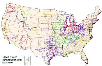
A power transmission network is referred to as a "grid". Multiple redundant lines between points on the network are provided so that power can be routed from any power plant to any load center, through a variety of routes, based on the economics of the transmission path and the cost of power. Much analysis is done by transmission companies to determine the maximum reliable capacity of each line, which, due to system stability considerations, may be less than the physical or thermal limit of the line. Deregulation of electricity companies in many countries has led to renewed interest in reliable economic design of transmission networks. However, in some places the gaming of a deregulated energy system has led to disaster, such as that which occurred during the California electricity crisis of 2000 and 2001.[2]
[edit] Overhead transmission
Overhead conductors are not covered by insulation. The conductor material is nearly always an aluminum alloy, made into several strands and possibly reinforced with steel strands. Copper was sometimes used for overhead transmission but aluminum is lower in weight for equivalent performance, and much lower in cost. Overhead conductors are a commodity supplied by several companies worldwide. Improved conductor material and shapes are regularly used to allow increased capacity and modernize transmission circuits. Conductor sizes range from #6 American wire gauge (about 12 square millimeters) to 1,590,000 circular mils area (about 750 square millimeters), with varying resistance and current-carrying capacity. Thicker wires would lead to a relatively small increase in capacity due to the skin effect, that causes most of the current to flow close to the surface of the wire.
Today, transmission-level voltages are usually considered to be 110 kV and above. Lower voltages such as 66 kV and 33 kV are usually considered sub-transmission voltages but are occasionally used on long lines with light loads. Voltages less than 33 kV are usually used for distribution. Voltages above 230 kV are considered extra high voltage and require different designs compared to equipment used at lower voltages.
Since overhead transmission lines are uninsulated wire, design of these lines requires minimum clearances to be observed to maintain safety. During adverse weather conditions of high wind and low temperatures, overhead conductors can exhibit wind-induced oscillations which can encroach on their designed clearances. Depending on the frequency and amplitude of oscillation, the motion can be termed gallop or flutter.
[edit] Underground transmission
Electric power can also be transmitted by underground power cables instead of overhead power lines. They can assist the transmission of power across:
- Densely populated urban areas
- Areas where land is unavailable or planning consent is difficult
- Rivers and other natural obstacles
- Land with outstanding natural or environmental heritage
- Areas of significant or prestigious infrastructural development
- Land whose value must be maintained for future urban expansion and rural development
Some other advantages of underground power cables:
- Less subject to damage from severe weather conditions (mainly wind and freezing)
- Greatly reduced emission, into the surrounding area, of electromagnetic fields (EMF). All electric currents generate EMF, but the shielding provided by the earth surrounding underground cables restricts their range and power. See section below, "Health concerns".
- Underground cables need a narrower surrounding strip of about 1- 10 meters to install, whereas an overhead line requires a surrounding strip of about 20- 200 meters wide to be kept permanently clear for safety, maintenance and repair.
Some disadvantages of underground power cables:
- Undergrounding is more expensive, since the cost of burying cables at transmission voltages is several times greater than overhead power lines, and the life-cycle cost of an underground power cable is two to four times the cost of an overhead power line.[3] According to the British Stakeholder Advisory Group on ELF EMFs[4], the cost is around GBP 10M/km, compared to GBP 0.5-1M/km for overhead lines. This is mainly due to the limit of the physical properties of the insulation placed during installation, keeping the runs to hundreds of meters between splices, which are most commonly placed in manholes or splice-boxes for repairs.
- Whereas finding and repairing overhead wire breaks can be accomplished in hours, underground repairs can take days or weeks[5], and for this reason redundant lines are run.
- Operations are more difficult since the high reactive power of underground cables produces large charging currents and so makes voltage control more difficult.[6]
The advantages can in some cases outweigh the disadvantages of the higher investment cost, and more expensive maintenance and management.
Most high-voltage underground cables for power transmission that are currently sold on the market are insulated by a sheath of cross-linked polyethylene (XLPE). Some cable may have a lead jacket in conjunction with XLPE insulation to allow for fiber optics to be seamlessly integrated within the cable. Before 1960, underground power cables were insulated with oil and paper and ran in a rigid steel pipe, or a semi-rigid aluminum or lead jacket or sheath. The oil was kept under pressure to prevent formation of voids that would allow partial discharges within the cable insulation. There are still many of these oil-and-paper insulated cables in use worldwide. Between 1960 and 1990, polymers became more widely used at distribution voltages, mostly EPDM (ethylene propylene diene M-class); however, their relative unreliability - particularly early XLPE - resulted in a slow uptake at transmission voltages. While cables of 330kV are commonly constructed using XLPE, this has occurred only in recent decades.
[edit] History

In the early days of commercial use of electric power, transmission of electric power at the same voltage as used by lighting and mechanical loads restricted the distance between generating plant and consumers. In 1882 generation was with direct current, which could not easily be increased in voltage for long-distance transmission. Different classes of loads – for example, lighting, fixed motors, and traction (railway) systems – required different voltages, and so used different generators and circuits. [7]
Due to this specialization of lines and because transmission was so inefficient that generators needed to be close by their loads, it seemed at the time that the industry would develop into what is now known as a distributed generation system with large numbers of small generators located nearby their loads. [8]
In 1886 in Great Barrington, Massachusetts, a 1kV AC distribution system was installed. That same year, AC power at 2kV, transmitted 30km, was installed at Cerchi, Italy. At an AIEE meeting on May 16, 1888, Nikola Tesla delivered a lecture entitled A New System of Alternating Current Motors and Transformers, describing the equipment which allowed efficient generation and use of polyphase alternating currents. The transformer, and Tesla's polyphase and single-phase induction motors, were essential for a combined AC distribution system for both lighting and machinery. Ownership of the rights to the Tesla patents was a key commercial advantage to the Westinghouse Company in offering a complete alternating current power system for both lighting and power.

Regarded as one of the most influential innovations for the use of electricity, the "universal system" used transformers to step-up voltage from generators to high-voltage transmission lines, and then to step-down voltage to local distribution circuits or industrial customers[9]. By a suitable choice of utility frequency, both lighting and motor loads could be served. Rotary converters and later mercury-arc valves and other rectifier equipment allowed DC load to be served by local conversion where needed. Even generating stations and loads using different frequencies could be interconnected using rotary converters. By using common generating plants for every type of load, important economies of scale were achieved, lower overall capital investment was required, load factor on each plant was increased allowing for higher efficiency, allowing for a lower cost of energy to the consumer and increased overall use of electric power.
By allowing multiple generating plants to be interconnected over a wide area, electricity production cost was reduced. The most efficient available plants could be used to supply the varying loads during the day. Reliability was improved and capital investment cost was reduced, since stand-by generating capacity could be shared over many more customers and a wider geographic area. Remote and low-cost sources of energy, such as hydroelectric power or mine-mouth coal, could be exploited to lower energy production cost. [9]
The first transmission of three-phase alternating current using high voltage took place in 1891 during the international electricity exhibition in Frankfurt. A 25 kV transmission line, approximately 175 kilometers long, connected Lauffen on the Neckar and Frankfurt.
Voltages used for electric power transmission increased throughout the 20th century. By 1914 fifty-five transmission systems each operating at more than 70 kV were in service. The highest voltage then used was 150 kV. [10]
The rapid industrialization in the 20th century made electrical transmission lines and grids a critical part of the economic infrastructure in most industrialized nations. Interconnection of local generation plants and small distribution networks was greatly spurred by the requirements of World War I, where large electrical generating plants were built by governments to provide power to munitions factories; later these plants were connected to supply civil load through long-distance transmission. [11]
[edit] Bulk power transmission
Engineers design transmission networks to transport the energy as efficiently as feasible, while at the same time taking into account economic factors, network safety and redundancy. These networks use components such as power lines, cables, circuit breakers, switches and transformers.
Transmission efficiency is improved by increasing the voltage using a step-up transformer, which reduces the current in the conductors, while keeping the power transmitted nearly equal to the power input. The reduced current flowing through the conductor reduces the losses in the conductor and since, according to Joule's Law, the losses are proportional to the square of the current, halving the current makes the transmission loss one quarter the original value.
A transmission grid is a network of power stations, transmission circuits, and substations. Energy is usually transmitted within the grid with three-phase AC. DC systems require relatively costly conversion equipment which may be economically justified for particular projects. Single phase AC is used only for distribution to end users since it is not usable for large polyphase induction motors. In the 19th century two-phase transmission was used, but required either three wires with unequal currents or four wires. Higher order phase systems require more than three wires, but deliver marginal benefits.
The capital cost of electric power stations is so high, and electric demand is so variable, that it is often cheaper to import some portion of the variable load than to generate it locally. Because nearby loads are often correlated (hot weather in the Southwest portion of the United States might cause many people there to turn on their air conditioners), imported electricity must often come from far away. Because of the economics of load balancing, wide area transmission grids now span across countries and even large portions of continents. The web of interconnections between power producers and consumers ensures that power can flow even if a few links are inoperative.
The unvarying (or slowly varying over many hours) portion of the electric demand is known as the "base load", and is generally served best by large facilities (and therefore efficient due to economies of scale) with low variable costs for fuel and operations, i.e. nuclear, coal, hydro. Renewables such as solar, wind, ocean/tidal, etc. are not considered "base load" but can still add power to the grid. Smaller- and higher-cost sources such as combined cycle or combustion turbine plants that run on natural gas are then added as needed.

Long-distance transmission of electricity (thousands of kilometers) is cheap and efficient, with costs of US$ 0.005 to 0.02 per kilowatt-hour (compared to annual averaged large producer costs of US$ 0.01 to US$ 0.025 per kilowatt-hour, retail rates upwards of US$ 0.10 per kilowatt-hour, and multiples of retail for instantaneous suppliers at unpredicted highest demand moments).[12] Thus distant suppliers can be cheaper than local sources (e.g. New York City buys a lot of electricity from Canada). Multiple local sources (even if more expensive and infrequently used) can make the transmission grid more fault tolerant to weather and other disasters that can disconnect distant suppliers.
Long distance transmission allows remote renewable energy resources to be used to displace fossil fuel consumption. Hydro and wind sources can't be moved closer to high population cities, and solar costs are lowest in remote areas where local power needs are the least. Connection costs alone can determine whether any particular renewable alternative is economically sensible. Costs can be prohibitive for transmission lines, but various proposals for massive infrastructure investment in high capacity, very long distance super grid transmission networks could be recovered with modest usage fees.
[edit] Grid input
At the generating plants the energy is produced at a relatively low voltage between about 2300 volts and 30,000 volts, depending on the size of the unit. The generator terminal voltage is then stepped up by the power station transformer to a higher voltage (115 kV to 765 kV AC, varying by country) for transmission over long distances.
[edit] Losses
Transmitting electricity at high voltage reduces the fraction of energy lost to Joule heating. For a given amount of power, a higher voltage reduces the current and thus the resistive losses in the conductor. For example, raising the voltage by a factor of 10 reduces the current by a corresponding factor of 10 and therefore the  losses by a factor of 100, provided the same sized conductors are used in both cases. Even if the conductor size is reduced x10 to match the lower current the losses are still reduced x10. Long distance transmission is typically done with overhead lines at voltages of 115 to 1,200 kV. At extremely high voltages, more than 2,000 kV between conductor and ground, corona discharge losses are so large that they can offset the lower resistance loss in the line conductors.
Transmission and distribution losses in the USA were estimated at 7.2% in 1995 [2], and in the UK at 7.4% in 1998. [3]
As of 1980, the longest cost-effective distance for electricity was 4,000 miles (7,000 km), although all present transmission lines are considerably shorter.[4]
In an alternating current circuit, the inductance and capacitance of the phase conductors can be significant. The currents that flow in these components of the circuit impedance constitute reactive power, which transmits no energy to the load. Reactive current flow causes extra losses in the transmission circuit. The ratio of real power (transmitted to the load) to apparent power is the power factor. As reactive current increases, the reactive power increases and the power factor decreases. For systems with low power factors, losses are higher than for systems with high power factors. Utilities add capacitor banks and other components throughout the system — such as phase-shifting transformers, static VAR compensators, physical transposition of the phase conductors, and flexible AC transmission systems (FACTS) — to control reactive power flow for reduction of losses and stabilization of system voltage.
[edit] Transmission grid exit
At the substations, transformers are again used to step the voltage down to a lower voltage for distribution to commercial and residential users. This distribution is accomplished with a combination of sub-transmission (33 kV to 115 kV, varying by country and customer requirements) and distribution (3.3 to 25 kV). Finally, at the point of use, the energy is transformed to low voltage (100 to 600 V, varying by country and customer requirements - see Mains power systems).
[edit] High-voltage direct current
High voltage direct current (HVDC) is used to transmit large amounts of power over long distances or for interconnections between asynchronous grids. When electrical energy is required to be transmitted over very long distances, it is more economical to transmit using direct current instead of alternating current. For a long transmission line, the lower losses and reduced construction cost of a DC line can offset the additional cost of converter stations at each end. Also, at high AC voltages, significant (although economically acceptable) amounts of energy are lost due to corona discharge, the capacitance between phases or, in the case of buried cables, between phases and the soil or water in which the cable is buried.
HVDC links are sometimes used to stabilize against control problems with the AC electricity flow. In other words, to transmit AC power as AC when needed in either direction between Seattle and Boston would require the (highly challenging) continuous real-time adjustment of the relative phase of the two electrical grids. With HVDC instead the interconnection would: (1) Convert AC in Seattle into HVDC. (2) Use HVDC for the three thousand miles of cross country transmission. Then (3) convert the HVDC to locally synchronized AC in Boston, and optionally in other cooperating cities along the transmission route. One prominent example of such a transmission line is the Pacific DC Intertie located in the Western United States.
[edit] Limitations
The amount of power that can be sent over a transmission line is limited. The origins of the limits vary depending on the length of the line. For a short line, the heating of conductors due to line losses sets a "thermal" limit. If too much current is drawn, conductors may sag too close to the ground, or conductors and equipment may be damaged by overheating. For intermediate-length lines on the order of 100 km (60 miles), the limit is set by the voltage drop in the line. For longer AC lines, system stability sets the limit to the power that can be transferred. Approximately, the power flowing over an AC line is proportional to the sine of the phase angle of the voltage at the receiving and transmitting ends. Since this angle varies depending on system loading and generation, it is undesirable for the angle to approach 90 degrees. Very approximately, the allowable product of line length and maximum load is proportional to the square of the system voltage. Series capacitors or phase-shifting transformers are used on long lines to improve stability. High-voltage direct current lines are restricted only by thermal and voltage drop limits, since the phase angle is not material to their operation.
Up to now, it has been almost impossible to foresee the temperature distribution along the cable route, so that the maximum applicable current load was usually set as a compromise between understanding of operation conditions and risk minimization. The availability of industrial Distributed Temperature Sensing (DTS) systems that measure in real time temperatures all along the cable is a first step in monitoring the transmission system capacity. This monitoring solution is based on using passive optical fibers as temperature sensors, either integrated directly inside a high voltage cable or mounted externally on the cable insulation. A solution for overhead lines is also available. In this case the optical fiber is integrated into the core of a phase wire of overhead transmission lines (OPPC). The integrated Dynamic Cable Rating (DCR) or also called Real Time Thermal Rating (RTTR) solution enables not only to continuously monitor the temperature of a high voltage cable circuit in real time, but to safely utilize the existing network capacity to its maximum. Furthermore it provides the ability to the operator to predict the behavior of the transmission system upon major changes made to its initial operating conditions.
[edit] Control
To ensure safe and predictable operation the components of the transmission system are controlled with generators, switches, circuit breakers and loads. The voltage, power, frequency, load factor, and reliability capabilities of the transmission system are designed to provide cost effective performance for the customers.
[edit] Load balancing
The transmission system provides for base load and peak load capability, with safety and fault tolerance margins. The peak load times vary by region largely due to the industry mix. In very hot and very cold climates home air conditioning and heating loads have an effect on the overall load. They are typically highest in the late afternoon in the hottest part of the year and in mid-mornings and mid-evenings in the coldest part of the year. This makes the power requirements vary by the season and the time of day. Distribution system designs always take the base load and the peak load into consideration.
The transmission system usually does not have a large buffering capability to match the loads with the generation. Thus generation has to be kept matched to the load, to prevent overloading failures of the generation equipment.
Multiple sources and loads can be connected to the transmission system and they must be controlled to provide orderly transfer of power. In centralized power generation, only local control of generation is necessary, and it involves synchronization of the generation units, to prevent large transients and overload conditions.
In distributed power generation the generators are geographically distributed and the process to bring them online and offline must be carefully controlled. The load control signals can either be sent on separate lines or on the power lines themselves. To load balance the voltage and frequency can be used as a signaling mechanism.
In voltage signaling the variation of voltage is used to increase generation. The power added by any system increases as the line voltage decreases. This arrangement is stable in principle. Voltage based regulation is complex to use in mesh networks, since the individual components and setpoints would need to be reconfigured every time a new generator is added to the mesh.
In frequency signaling, the generating units match the frequency of the power transmission system. In Droop speed control, if the frequency decreases, the power is increased. (The drop in line frequency is an indication that the increased load is causing the generators to slow down.)
Wind turbines, v2g and other distributed storage and generation systems can be connected to the power grid, and interact with it to improve system operation.
[edit] Failure protection
Under excess load conditions, the system can be designed to fail gracefully rather than all at once. Brownouts occur when the supply power drops below the demand. Blackouts occur when the supply fails completely.
Rolling blackouts, or load shedding, are intentionally-engineered electrical power outages, used to distribute insufficient power when the demand for electricity exceeds the supply.
[edit] Communications
Operators of long transmission lines require reliable communications for control of the power grid and, often, associated generation and distribution facilities. Fault-sensing protection relays at each end of the line must communicate to monitor the flow of power into and out of the protected line section so that faulted conductors or equipment can be quickly de-energized and the balance of the system restored. Protection of the transmission line from short circuits and other faults is usually so critical that common carrier telecommunications are insufficiently reliable. In remote areas a common carrier may not be available at all. Communication systems associated with a transmission project may use:
Rarely, and for short distances, a utility will use pilot-wires strung along the transmission line path. Leased circuits from common carriers are not preferred since availability is not under control of the electric power transmission organization.
Transmission lines can also be used to carry data: this is called power-line carrier, or PLC. PLC signals can be easily received with a radio for the long wave range.
Optical fibers can be included in the stranded conductors of a transmission line, in the overhead shield wires. These cables are known as OPGW or Optical Ground Wire. Sometimes a standalone cable is used, ADSS or All Dielectric Self Supporting cable, attached to the transmission line cross arms.
Some jurisdictions, such as Minnesota, prohibit energy transmission companies from selling surplus communication bandwidth or acting as a telecommunications common carrier. Where the regulatory structure permits, the utility can sell capacity in extra dark fibers to a common carrier, providing another revenue stream for the line.
[edit] Electricity market reform
|
|
It has been suggested that this article or section be merged into Electricity market. (Discuss) |
Some regulators regard electric transmission to be a natural monopoly[13][14] and there are moves in many countries to separately regulate transmission (see Electricity market).
Spain was the first country to establish a Regional Transmission Organization. In that country transmission operations and market operations are controlled by separate companies. The transmission system operator is Red Eléctrica de España (REE) and the wholesale electricity market operator is Operador del Mercado Ibérico de Energía - Polo Español, S.A. (OMEL) [5]. Spain's transmission system is interconnected with those of France, Portugal, and Morocco.
In the United States and parts of Canada, electrical transmission companies operate independently of generation and distribution companies.
[edit] Merchant transmission
Merchant transmission is an arrangement where a third party constructs and operates electric transmission lines through the franchise area of an unrelated utility. Advocates of merchant transmission[who?] claim that this will create competition to construct the most efficient and lowest cost additions to the transmission grid. Merchant transmission projects typically involve DC lines because it is easier to limit flows to paying customers.
The only operating merchant transmission project in the United States is the Cross Sound Cable from Long Island, New York to New Haven, Connecticut, although additional projects have been proposed.
There is only one unregulated or market interconnector in Australia: Basslink between Tasmania and Victoria. Two DC links originally implemented as market interconnectors Directlink and Murraylink have been converted to regulated interconnectors. NEMMCO
A major barrier to wider adoption of merchant transmission is the difficulty in identifying who benefits from the facility so that the beneficiaries will pay the toll. Also, it is difficult for a merchant transmission line to compete when the alternative transmission lines are subsidized by other utility businesses.[15]
[edit] Health concerns
Some research has found that exposure to elevated levels of EMF (electromagnetic fields), including ELF (extremely low frequency) fields, such as those originating from electric power transmission lines, may be implicated in a number of adverse health effects. These include, but are not limited to, childhood leukemia [16][17], Alzheimer's[18], adult leukemia[19], breast cancer[20], neurodegenerative diseases (such as amyotrophic lateral sclerosis)[21][22][23], Miscarriage[24][25][26], and clinical depression. Although there seems to be a small statistical correlation between various diseases and living near power lines, any physical mechanism is not clear. One proposed mechanism is that the electric fields around power lines attract aerosol pollutants.[27][28]
One response to the potential dangers of overhead power lines is to place them underground. The earth and enclosures surrounding underground cables prevent the electric field from radiating significantly beyond the power lines, and greatly reduce the magnetic field strength radiating from the power lines, into the surrounding area.[29] However, the cost of burying and maintaining cables at transmission voltages is several times greater than overhead power lines (see section above, "Underground transmission").
[edit] Government policy
Historically, local governments have exercised authority over the grid and have significant disincentives to take action that would benefit states other than their own. Localities with cheap electricity have a disincentive to making interstate commerce in electricity trading easier, since other regions will be able to compete for local energy and drive up rates. Some regulators in Maine for example do not wish to address congestion problems because the congestion serves to keep Maine rates low.[30] Further, vocal local constituencies can block or slow permitting by pointing to visual impact, environmental, and perceived health concerns. In the US, generation is growing 4 times faster than transmission, but big transmission upgrades require the coordination of multiple states, a multitude of interlocking permits, and cooperation between a significant portion of the 500 companies that own the grid. From a policy perspective, the control of the grid is balkanized, and even former Energy secretary Bill Richardson refers to it as a "third world grid". There have been efforts in the EU and US to confront the problem. The US national security interest in significantly growing transmission capacity drove passage of the 2005 energy act giving the Department of Energy the authority to approve transmission if states refuse to act. However, soon after using its power to designate two National Interest Electric Transmission Corridors, 14 senators signed a letter stating the DOE was being too aggressive[31].
[edit] Special transmission
[edit] Grids for railways
In some countries where electric trains run on low frequency AC (e.g. 16.7 Hz and 25 Hz) power, there are separate single phase traction power networks operated by the railways. These grids are fed by separate generators in some traction powerstations or by traction current converter plants from the public three phase AC network.
[edit] Radio frequency power transmission
Radio and television broadcasters use specialized transmission lines to carry the output of high-power transmitters to the antenna.
[edit] Superconducting cables
High-temperature superconductors promise to revolutionize power distribution by providing lossless transmission of electrical power. The development of superconductors with transition temperatures higher than the boiling point of liquid nitrogen has made the concept of superconducting power lines commercially feasible, at least for high-load applications. [32] It has been estimated that the waste would be halved using this method, since the necessary refrigeration equipment would consume about half the power saved by the elimination of the majority of resistive losses. In one hypothetical future system called a SuperGrid, the cost of cooling would be eliminated by coupling the transmission line with a liquid hydrogen pipeline.
Superconducting cables are particularly suited to high load density areas such as the business district of large cities, where purchase of an easement for cables would be very costly. [6]
[edit] Single wire earth return
Single wire earth return (SWER) or single wire ground return is a single-wire transmission line for supplying single-phase electrical power for an electrical grid to remote areas at low cost. It is principally used for rural electrification, but also finds use for larger isolated loads such as water pumps, and light rail. Single wire earth return is also used for HVDC over submarine power cables.
[edit] Wireless power transmission
Every radio transmitter emits power wirelessly. Both Nikola Tesla and Hidetsugu Yagi attempted to devise systems for large scale wireless power transmission. Tesla claimed to have succeeded.[33][34][35][36][37] Yagi also proposed a similar concept, but the engineering problems proved to be more onerous than conventional systems. His work, however, led to the invention of the Yagi antenna.
Another form of wireless power transmission has been studied for transmission of power from solar power satellites to the earth. A high power array of microwave transmitters would beam power to a rectenna. Major engineering and economic challenges face any solar power satellite project.
Another form is the operation of a crystal radio powered by the radio station it is tuned to; however, the energetic efficiency is extremely low. Small scale wireless power was demonstrated as early as 1831 by Michael Faraday. By 1888, Heinrich Rudolf Hertz had proven that natural radio waves exist and can be captured.
[edit] Records
- Highest capacity system: 6,300 MW HVDC Itaipu (Brazil) (±600 kV DC)[38]
- Highest transmission voltage (AC): 1,150 kV on Powerline Ekibastuz-Kokshetau (Kazakhstan)
- Highest pylons: Yangtze River Crossing (height: 345 m (1,132 ft))
- Longest power line: Inga-Shaba (length: 1,700 kilometres (1,056 mi))
- Longest span of power line: 5,376 m (17,638 ft) at Ameralik Span
- Longest submarine cables:
- NorNed, North Sea - (length of submarine/underground cable: 580 kilometres (360 mi))
- Basslink, Bass Strait - (length of submarine/underground cable: 290 kilometres (180 mi), total length: 357.4 kilometres (222 mi))
- Baltic-Cable, Baltic Sea - (length of submarine/underground cable: 249 kilometres (155 mi), total length: 261 kilometres (162 mi))
[edit] See also
| Look up grid electricity in Wiktionary, the free dictionary. |
[edit] Notes
- ^ (pdf)A Primer on Electric Utilities, Deregulation, and Restructuring of U.S. Electricity Markets. United States Department of Energy Federal Energy Management Program (FEMP). 2002-05. http://www1.eere.energy.gov/femp/pdfs/primer.pdf. Retrieved on 2008-12-27.
- ^ Staff Report: PRICE MANIPULATION IN WESTERN MARKETS DOCKET NO. PA02-2-000. United States Department of Energy Federal Energy Regulatory Commission. 2003-03-26. http://www.ferc.gov/industries/electric/indus-act/wec/enron/summary-findings.pdf. Retrieved on 2008-12-27.
- ^ Edison Electric Institute - Underground Vs. Overhead Distribution Wires: Issues to Consider
- ^ "SAGE first interim assessment: Power Lines and Property, Wiring in Homes, and Electrical Equipment in Homes"
- ^ Should Power Lines be Underground?
- ^ Weedy, Stephenson, and others
- ^ Hughes
- ^ National Council on Electricity Policy (pdf). Electricity Transmission: A primer. http://www.oe.energy.gov/DocumentsandMedia/primer.pdf.
- ^ a b Thomas P. Hughes. Networks of Power: Electrification in Western Society, 1880-1930. Baltimore: Johns Hopkins University Press. p. 119-122. ISBN 0801846145. http://books.google.com/books?id=g07Q9M4agp4C&pg=PA122&lpg=PA122&dq=westinghouse+%22universal+system%22&source=bl&ots=BAyz1BrjNU&sig=xkSMfJqxs1H3dm1YMsrXx4vt4L0&hl=en&sa=X&oi=book_result&resnum=1&ct=result#PPA122,M1.
- ^ Bureau of Census data reprinted in Hughes, pp. 282-283
- ^ Hughes, pp. 293-295
- ^ "Present Limits of Very Long Distance Transmission Systems"
- ^ Raghuvir Srinivasan (August 15, 2004). "Power transmission business is a natural monopoly". The Hindu Business Line. The Hindu. http://www.thehindubusinessline.com/iw/2004/08/15/stories/2004081501201300.htm. Retrieved on 2008-01-31.
- ^ Lynne Kiesling (August 18, 2003). "Rethink the Natural Monopoly Justification of Electricity Regulation". Reason Foundation. http://www.reason.org/commentaries/kiesling_20030818b.shtml. Retrieved on 2008-01-31.
- ^ Fiona Woolf (February 2003). Global Transmission Expansion. Pennwell Books. pp. 226, 247. ISBN 0-87814-862-0.
- ^ Albohm, Anders; Elisabeth Cardis, Adele Green, Martha Linet, David Savitz, Anthony Swerdlow (December 2001). "Review of the Epidemiologic Literature on EMF and Health". Environ Health Perspect. 109 (S6). http://www.ehponline.org/members/2001/suppl-6/911-933ahlbom/ahlbom-full.html.
- ^ Greenland, Sander; W Kaune, C Poole, M Kelsh, A Sheppard (November 2000). "A pooled analysis of magnetic fields, wire codes, and childhood leukemia. Childhood Leukemia-EMF Study Group". Epidemiology 11 (6): 624–34. http://www.ncbi.nlm.nih.gov/pubmed/11055621.
- ^ García, AM; A Sisternas, SP Hoyos (April 2008). "Occupational exposure to extremely low frequency electric and magnetic fields and Alzheimer disease: a meta-analysis". Int J Epidemiol 37 (2): 329–40. PMID 18245151. http://www.ncbi.nlm.nih.gov/pubmed/18245151.
- ^ Tynes, Tore; L Klaeboe, T Haldorsen (May 2003). "Residential and occupational exposure to 50 Hz magnetic fields and malignant melanoma: a population based study". Occup Environ Med 60 (5): 343–7. doi:. PMID 12709519. http://www.ncbi.nlm.nih.gov/sites/entrez?db=pubmed&cmd=Retrieve&dopt=Abstract&list_uids=12709519.
- ^ Hansen, J (January 2001). "Increased breast cancer risk among women who work predominantly at night". Epidemiology 12 (1): 74–7. doi:. http://www.ncbi.nlm.nih.gov/sites/entrez?db=pubmed&cmd=Retrieve&dopt=Abstract&list_uids=11138824.
- ^ Feychting, Maria; Anders Ahlbom, F Jonsson, NL Pederson (July 2003). "Occupational magnetic field exposure and neurodegenerative disease". Epidemiology 14 (4): 413–9. doi:. http://www.ncbi.nlm.nih.gov/sites/entrez?db=pubmed&cmd=Retrieve&dopt=Abstract&list_uids=12843764.
- ^ Hakansson, Niklas; P Gustavsson, Birgitte Floderus, Christof Johanen (July 2003). "Neurodegenerative diseases in welders and other workers exposed to high levels of magnetic fields". Epidemiology 14 (4): 420–6. doi:. http://www.ncbi.nlm.nih.gov/sites/entrez?db=pubmed&cmd=Retrieve&dopt=Abstract&list_uids=12843765.
- ^ Albohm, Anders (2001). "Neurodegenerative diseases, suicide and depressive symptoms in relation to EMF.". Bioelectromagnetics (Suppl 5): S132–43. http://www3.interscience.wiley.com/cgi-bin/abstract/76509952/.
- ^ Lee, GM; Michael Yost, RR Neutra, L Hristova, RA Hiatt (January 2002). "A nested case-control study of residential and personal magnetic field measures and miscarriages". Epidemiology 13 (1): 21–31. doi:. http://www.ncbi.nlm.nih.gov/sites/entrez?Db=pubmed&Cmd=ShowDetailView&TermToSearch=11805582.
- ^ Li, De-Kun; Roxana Odouli, S Wi, T Janevic, I Golditch, TD Bracken, R Senior, R Rankin, R Iriye (January 2002). "A population-based prospective cohort study of personal exposure to magnetic fields during pregnancy and the risk of miscarriage". Epidemiology 13 (1): 9–20. doi:. http://www.ncbi.nlm.nih.gov/sites/entrez?Db=pubmed&Cmd=ShowDetailView&TermToSearch=11805581.
- ^ Cao, YN; Y Zhang, Y Liu (August 2006). "Effects of exposure to extremely low frequency electromagnetic fields on reproduction of female mice and development of offsprings". Zhonghua Lao Dong Wei Sheng Zhi Ye Bing Za Zhi 24 (8): 468–70. http://www.ncbi.nlm.nih.gov/sites/entrez?Db=pubmed&Cmd=ShowDetailView&TermToSearch=16978513.
- ^ Fews, Peter; Denis Henshaw, Paul Keitch, Julie Close, Richard Wilding (December 1999). "Increased exposure to pollutant aerosols under high voltage power lines". Int J Radiat Biol. 75 (12): 1505–21. doi:. http://www.ncbi.nlm.nih.gov/entrez/query.fcgi?db=pubmed&cmd=Retrieve&dopt=Abstract&list_uids=10622257.
- ^ Fews, Peter; Denis Henshaw, Richard Wilding, Paul Keitch (December 1999). "Corona ions from powerlines and increased exposure to pollutant aerosols". Int J Radiat Biol. 75 (12): 1523–31. doi:. http://www.ncbi.nlm.nih.gov/entrez/query.fcgi?db=pubmed&cmd=Retrieve&dopt=Abstract&list_uids=10622258.
- ^ UK National Grid EMF information site
- ^ National Council on Electricity Policy (pdf). Electricity Transmission: A primer. p. 32 (41 in pdf). http://www.oe.energy.gov/DocumentsandMedia/primer.pdf.
- ^ [|Wald, Matthew] (2008-08-27). Wind Energy Bumps Into Power Grid’s Limits. New York Times. p. A1. http://www.nytimes.com/2008/08/27/business/27grid.html?_r=2&ref=business&oref=slogin. Retrieved on 2008-12-12.
- ^ Jacob Oestergaard et al., Energy losses of superconducting power transmission cables in the grid, [1]
- ^ "The Transmission of Electrical Energy Without Wires," Electrical World, March 5, 1904
- ^ Norrie, H. S., "Induction Coils: How to make, use, and repair them". Norman H. Schneider, 1907, New York. 4th edition.
- ^ Electrical Experimenter, January 1919. pg. 615
- ^ Tesla: Man Out of Time By Margaret Cheney. Page 174.
- ^ Martin, T. C., & Tesla, N. (1894). The inventions, researches and writings of Nikola Tesla, with special reference to his work in polyphase currents and high potential lighting. New York: The Electrical Engineer. Page 188.
- ^ "Energy Systems, Environment and Development". Advanced Technology Assessment Systems (Global Energy Network Institute) (Issue 6). Autumn 1991. http://www.geni.org/globalenergy/library/technical-articles/transmission/united-nations/center-for-science-and-technology-for-development/advanced-technology-assessment-system/energy-systems-environment-and-development.shtml. Retrieved on 2008-12-27.
[edit] Further reading
- Grigsby, L. L., et al. The Electric Power Engineering Handbook. USA: CRC Press. (2001). ISBN 0-8493-8578-4
- Thomas P. Hughes, Networks of Power: Electrification in Western Society 1880-1930, The Johns Hopkins University Press,Baltimore 1983 ISBN 0-8018-2873-2, an excellent overview of development during the first 50 years of commercial electric power
- Westinghouse Electric Corporation, "Electric power transmission patents; Tesla polyphase system". (Transmission of power; polyphase system; Tesla patents)
- Pansini, Anthony J, E.E., P.E. undergrounding electric lines. USA Hayden Book Co, 1978. ISBN 0-8104-0827-9
[edit] External links
- Japan: World's First In-Grid High-Temperature Superconducting Power Cable System
- A Power Grid for the Hydrogen Economy: Overview/A Continental SuperGrid
- Global Energy Network Institute (GENI) - The GENI Initiative focuses on linking renewable energy resources around the world using international electricity transmission.
- Union for the Co-ordination of Transmission of Electricity (UCTE), the association of transmission system operators in continental Europe, running one of the two largest power transmission systems in the world
- Non-Ionizing Radiation, Part 1: Static and Extremely Low-Frequency (ELF) Electric and Magnetic Fields (2002) by the IARC -- Link Broken.
- A Simulation of the Power Grid - The Trustworthy Cyber Infrastructure for the Power Grid (TCIP) group at the University of Illinois at Urbana-Champaign has developed lessons and an applet which illustrate the transmission of electricity from generators to energy consumers, and allows the user to manipulate generation, consumption, and power flow.
|
|||||||||||||||||||||||||

