3D projection
From Wikipedia, the free encyclopedia
 |
| Part of a series on: |
| Graphical projection |
|
Other
|
3D projection is any method of mapping three-dimensional points to a two-dimensional plane. As most current methods for displaying graphical data are based on planar two-dimensional media, the use of this type of projection is widespread, especially in computer graphics, engineering and drafting.
Contents |
[edit] Orthographic projection
|
|
It has been suggested that this article or section be merged with Orthographic projection. (Discuss) |
Orthographic projections are a small set of transforms often used to show profile, detail or precise measurements of a three dimensional object. Common names for orthographic projections include plan, cross-section, bird's-eye, and elevation.
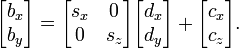
If the normal of the viewing plane (the camera direction) is parallel to one of the 3D axes, the mathematical transformation is as follows; To project the 3D point ax, ay, az onto the 2D point bx, by using an orthographic projection parallel to the y axis (profile view), the following equations can be used:
- bx = sxax + cx
- by = szaz + cz
where the vector s is an arbitrary scale factor, and c is an arbitrary offset. These constants are optional, and can be used to properly align the viewport. The projection can be shown using Matrix notation (introducing a temporary vector d for clarity)

While orthographically projected images represent the three dimensional nature of the object projected, they do not represent the object as it would be recorded photographically or perceived by a viewer observing it directly. In particular, parallel lengths at all points in an orthographically projected image are of the same scale regardless of whether they are far away or near to the virtual viewer. As a result, lengths near to the viewer appear foreshortened.
[edit] Perspective projection
|
|
It has been suggested that this article or section be merged with Perspective (graphical). (Discuss) |
- See also Transformation matrix
The perspective projection requires greater definition. A conceptual aid to understanding the mechanics of this projection involves treating the 2D projection as being viewed through a camera viewfinder. The camera's position, orientation, and field of view control the behavior of the projection transformation. The following variables are defined to describe this transformation:
 - the point in 3D space that is to be projected.
 - the location of the camera.
 - The rotation of the camera. When =<0,0,0>, and =<0,0,0>, the 3D vector <1,2,0> is projected to the 2D vector <1,2>.
 - the viewer's position relative to the display surface. [1]
Which results in:
 - the 2D projection of
  .
.
First, we define a point  as a translation of point into a coordinate system defined by
  . This is achieved by subtracting from and then applying a vector rotation matrix using
  to the result. This transformation is often called a camera transform (note that these calculations assume a left-handed system of axes): [2] [3]

Or, for those less comfortable with matrix multiplication. Signs of angles are inconsistent with matrix form:

This transformed point can then be projected onto the 2D plane using the formula (here, x/y is used as the projection plane, literature also may use x/z):[4]

Or, in matrix form using homogeneous coordinates:

and
The distance of the viewer from the display surface,  , directly relates to the field of view, where
 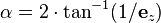 is the viewed angle. (Note: This assumes that you map the points (-1,-1) and (1,1) to the corners of your viewing surface)
Subsequent clipping and scaling operations may be necessary to map the 2D plane onto any particular display media.
[edit] Diagram

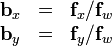
To determine which screen x coordinate corresponds to a point at Ax,Az multiply the point coordinates by:

the same works for the screen y coordinate:

(where Ax and Ay are coordinates occupied by the object before the perspective transform)
[edit] See also
- Computer graphics
- 3D computer graphics
- Graphics card
- Transform and lighting
- Texture mapping
- Perspective (graphical)
- Homography
- Homogeneous coordinates
[edit] References
- ^ Ingrid Carlbom, Joseph Paciorek (December 1978). Planar Geometric Projections and Viewing Transformations. v.10 n.4. ACM Computing Surveys (CSUR). pp. 465–502. doi:.
- ^ Riley, K F (2006). Mathematical Methods for Physics and Engineering. Cambridge University Press. pp. 931,942. doi:. ISBN 0521679710.
- ^ Goldstein, Herbert (1980). Classical Mechanics 2nd Edn.. Reading, Mass.: Addison-Wesley Pub. Co.. pp. 146–148. ISBN 0201029189.
- ^ Sonka, M; Hlavac, V; Boyle, R (1995), Image Processing, Analysis & Machine Vision 2nd Edn., Chapman and Hall, pp. 14, ISBN 0412455706
[edit] Further reading
| Wikimedia Commons has media related to: 3D projection |
- Kenneth C. Finney (2004). 3D Game Programming All in One. Thomson Course. pp. 93. ISBN 159200136X. http://books.google.com/books?id=cknGqaHwPFkC&pg=PA93&dq=%223D+projection%22&ie=ISO-8859-1&output=html&sig=1ClwdV95eKLGbEgkcxb1PW1YjUk.

