Continuously variable transmission
From Wikipedia, the free encyclopedia
| Transmission types |
|---|
| Manual |
| Continuously variable |
| Bicycle gearing |
A continuously variable transmission (CVT) is a transmission which can change steplessly through an infinite number of effective gear ratios between maximum and minimum values. This contrasts with other mechanical transmissions that only allow a few different distinct gear ratios to be selected. The flexibility of a CVT allows the driving shaft to maintain a constant angular velocity over a range of output velocities. This can provide better fuel economy than other transmissions by enabling the engine to run at its most efficient revolutions per minute (RPM) for a range of vehicle speeds.
Contents |
[edit] Uses
Many small tractors for home and garden use have simple hydrostatic or rubber belt CVTs. For example, the John Deere Gator line of small utility vehicles use a belt with a conical pulley system. They can deliver a lot of power and can reach speeds of 10-15 MPH, all without need for a clutch or shift gears. Many new snowmobiles and motorscooters use CVTs. Virtually all snowmobile and motor scooter CVTs are rubber belt/variable pulley CVTs. Additionally, newer hybrids, such as the Toyota Prius or Camry, and the Honda Insight use CVT to maximize fuel efficiency.
Some combine harvesters have CVTs. The CVT allows the forward speed of the combine to be adjusted independently of the engine speed. This allows the operator to slow down and speed up as needed to accommodate variations in thickness of the crop.
CVTs have been used in aircraft electrical power generating systems since the 1950s and in SCCA Formula 500 race cars since the early 1970s. More recently, CVT systems have been developed for go-karts and have proven to increase performance and engine life expectancy. The Tomcar range of off-road vehicles also utilizes the CVT system.
Some drill presses and milling machines contain a pulley-based CVT where the output shaft has a pair of manually-adjustable conical pulley halves through which a wide drive belt from the motor loops. The pulley on the motor, however, is usually fixed in diameter, or may have a series of given-diameter steps to allow a selection of speed ranges. A handwheel on the drill press, marked with a scale corresponding to the desired machine speed, is mounted to a reduction gearing system for the operator to precisely control the width of the gap between the pulley halves. This gap width thus adjusts the gearing ratio between the motor's fixed pulley and the output shaft's variable pulley, changing speed of the chuck; a tensioner pulley is implemented in the belt transmission to take up or release the slack in the belt as the speed is altered. In most cases, however, the drill press' speed must be changed with the motor running.
[edit] Advantages and disadvantages
|
|
This article may contain original research or unverified claims. Please improve the article by adding references. See the talk page for details. (September 2008) |
[edit] Advantages
- CVTs can compensate for changing vehicle speeds, allowing the engine speed to remain at its level of peak efficiency. This improves fuel economy and by effect, exhaust emissions.
- CVTs operate smoothly since there are no gear changes which cause sudden jerks.
[edit] Disadvantages
- CVTs operate smoothly and efficiently, without spending energy to jerk the car during a shift. This can give a perception of low power, because many drivers expect a jerk when they begin to move the vehicle. However, the expected jerk of a non-CVT can be emulated by CVT control software, thus eliminating this marketing problem.[citation needed]
- Since the CVT keeps the engine turning at constant RPM over a wide range of vehicle speeds, pressing on the accelerator pedal will make the car move faster but does not change the sound coming from the engine as much as a conventional automatic transmission gear-shift. This confuses some drivers and leads to an impression of a lack of power. This can be considered a disadvantage if the driver desires to hear the engine change tone.
- CVT torque-handling capability is limited by the strength of their transmission medium (usually a belt or chain), and by their ability to withstand friction wear between torque source and transmission medium (in friction-driven CVTs). CVTs in production prior to 2005 are predominantly belt- or chain-driven and therefore typically limited to low-powered cars and other light-duty applications. Units using advanced lubricants, however, have been proven to support any amount of torque in production vehicles, including that used for buses, heavy trucks, and earth-moving equipment.
[edit] Types
[edit] Variable-diameter pulley (VDP) or Reeves drive
In this most common CVT system, [1] there are two V-belt pulleys that are split perpendicular to their axes of rotation, with a V-belt running between them. The gear ratio is changed by moving the two sections of one pulley closer together and the two sections of the other pulley farther apart. Due to the V-shaped cross section of the belt, this causes the belt to ride higher on one pulley and lower on the other. Doing this changes the effective diameters of the pulleys, which changes the overall gear ratio. The distance between the pulleys does not change, and neither does the length of the belt, so changing the gear ratio means both pulleys must be adjusted (one bigger, the other smaller) simultaneously to maintain the proper amount of tension on the belt.
The V-belt needs to be very stiff in the pulleys axial direction in order to only make short radial movements while sliding in and out of the pulleys. This can only be achieved by a chain and not by homogeneous rubber. To dive out of the pulleys one side of the belt must push. This again can only be done with a chain. Each element of the chain has conical sides, which perfectly fit to the pulley if the belt is running on the outermost radius. As the belt moves into the pulleys the contact area gets smaller. The contact area is proportional to the number of elements, thus the chain has lots of very small elements. The shape of the elements is governed by the static of a column. The pulley-radial thickness of the belt is a compromise between maximum gear ratio and torque. For the same reason the axis between the pulleys is as thin as possible. A film of lubricate is applied to the pulleys. It needs to be thick enough so that the pulley and the belt never touch and it must be thin enough in order to not waste power when each element dives into the lubrication film. Additionally the chain elements stabilize about 12 steel bands. Each band is thin enough so that it easily bends. If bending, it has a perfect conical surface on its side. In the stack of bands each bands corresponds to a slightly different gear ratio, and thus they slide over each other and need oil between them. Also the outer bands slide through the stabilizing chain, while the center band can be used as the chain linkage.
Diagrams:
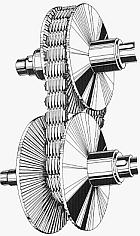
[edit] Toroidal or roller-based CVT
Toroidal CVTs are made up of discs and rollers that transmit power between the discs. The discs can be pictured as two almost conical parts, point to point, with the sides dished such that the two parts could fill the central hole of a torus. One disc is the input, and the other is the output (they do not quite touch). Power is transferred from one side to the other by rollers. When the roller's axis is perpendicular to the axis of the near-conical parts, it contacts the near-conical parts at same-diameter locations and thus gives a 1:1 gear ratio. The roller can be moved along the axis of the near-conical parts, changing angle as needed to maintain contact. This will cause the roller to contact the near-conical parts at varying and distinct diameters, giving a gear ratio of something other than 1:1. Systems may be partial or full toroidal. Full toroidal systems are the most efficient design while partial toroidals may still require a torque converter, and hence lose efficiency.
Diagrams:
[edit] Infinitely Variable Transmission (IVT)
A specific type of CVT is the infinitely variable transmission (IVT), in which the range of ratios of output shaft speed to input shaft speed includes a zero ratio that can be continuously approached from a defined "higher" ratio. A zero output speed (low gear) with a finite input speed implies an infinite input-to-output speed ratio, which can be continuously approached from a given finite input value with an IVT. Low gears are a reference to low ratios of output speed to input speed. This low ratio is taken to the extreme with IVTs, resulting in a "neutral", or non-driving "low" gear limit, in which the output speed is zero. Unlike neutral in a normal automotive transmission, IVT output rotation may be prevented because the backdriving (reverse IVT operation) ratio may be infinite, resulting in impossibly high backdriving torque; ratcheting IVT output may freely rotate forward, though.
The IVT dates back to before the 1930's; the original design converts rotary motion to oscillating motion and back to rotary motion using roller clutches.[2] The stroke of the intermediate oscillations is adjustable, varying the output speed of the shaft. This original design is still manufactured today, and an example and animation of this IVT can be found here. Paul B. Pires created a more compact (radially symmetric) variation that employs a ratchet mechanism instead of roller clutches, so it doesn't have to rely on friction to drive the output. An article and sketch of this variation can be found here
Most IVTs result from the combination of a CVT with a planetary gear system (which is also known as an epicyclic gear system) which enforces an IVT output shaft rotation speed which is equal to the difference between two other speeds within the IVT. This IVT configuration uses its CVT as a continuously variable regulator (CVR) of the rotation speed of any one of the three rotators of the planetary gear system (PGS). If two of the PGS rotator speeds are the input and output of the CVR, there is a setting of the CVR that results in the IVT output speed of zero. The maximum output/input ratio can be chosen from infinite practical possibilities through selection of additional input or output gear, pulley or sprocket sizes without affecting the zero output or the continuity of the whole system. The IVT is always engaged, even during its zero output adjustment.
IVTs can in some implementations offer better efficiency when compared to other CVTs as in the preferred range of operation because most of the power flows through the planetary gear system and not the controlling CVR. Torque transmission capability can also be increased. There's also possibility to stage power splits for further increase in efficiency, torque transmission capability and better maintenance of efficiency over a wide gear ratio range.
An example of a true IVT is the SIMKINETICS SIVAT that uses a ratcheting CVR. Its CVR ratcheting mechanism contributes minimal IVT output ripple across its range of ratios.
Another example of a true IVT is the Hydristor because the front unit connected to the engine can displace from zero to 27 cubic inches per revolution forward and zero to -10 cubic inches per revolution reverse. The rear unit is capable of zero to 75 cubic inches per revolution.
Diagrams:
[edit] Ratcheting CVT
The ratcheting CVT is a Transmission that relies on static friction and is based on a set of elements that successively become engaged and then disengaged between the driving system and the driven system, often using oscillating or indexing motion in conjunction with one-way clutches or ratchets that rectify and sum only "forward" motion. The transmission ratio is adjusted by changing linkage geometry within the oscillating elements, so that the summed maximum linkage speed is adjusted, even when the average linkage speed remains constant. Power is transferred from input to output only when the clutch or ratchet is engaged, and therefore when it is locked into a static friction mode where the driving & driven rotating surfaces momentarily rotate together without slippage.
These CVTs can transfer substantial torque because their static friction actually increases relative to torque throughput, so slippage is impossible in properly designed systems. Efficiency is generally high because most of the dynamic friction is caused by very slight transitional clutch speed changes. The drawback to ratcheting CVTs is vibration caused by the successive transition in speed required to accelerate the element which must supplant the previously operating & decelerating, power transmitting element.
Ratcheting CVTs are distinguished from VDPs and roller-based CVTs by being static friction-based devices, as opposed to being dynamic friction-based devices that waste significant energy through slippage of twisting surfaces. An example of a racheting CVT is one prototyped as a bicycle transmission protected under U.S. Patent #5516132 in which strong pedalling torque causes this mechanism to react against the spring, moving the ring gear/chainwheel assembly toward a concentric, lower gear position. When the pedalling torque relaxes to lower levels, the transmission self-adjusts toward higher gears, accompanied by an increase in transmission vibration.
A running prototype and functioning animation of a two stage ratcheting CVT can be found below:
[edit] Hydrostatic CVTs
Hydrostatic transmissions use a variable displacement pump and a hydraulic motor. All power is transmitted by hydraulic fluid. These types can generally transmit more torque, but can be sensitive to contamination. Some designs are also very expensive. However, they have the advantage that the hydraulic motor can be mounted directly to the wheel hub, allowing a more flexible suspension system and eliminating efficiency losses from friction in the drive shaft and differential components. This type of transmission is relatively easy to use because all forward and reverse speeds can be accessed using a single lever.
An integrated hydrostatic transaxle (IHT) uses a single housing for both hydraulic elements and gear-reducing elements. This type of transmission, most commonly manufactured by Hydro-Gear (as of 2008 - Tuff Torq may have taken the lead in 2006 and 2007 - this data needs a cite), has been effectively applied to a variety of inexpensive and expensive versions of ridden lawn mowers and garden tractors. Many versions of riding lawn mowers and garden tractors propelled by a hydrostatic transmission are capable of pulling a reverse tine tiller and even a single bladed plow.
One class of riding lawn mower that has recently gained in popularity with consumers is zero turning radius mowers. These mowers have traditionally been powered with wheel hub mounted hydraulic motors driven by continuously variable pumps, but this design is relatively expensive. Hydro-Gear, created the first cost-effective integrated hydrostatic transaxle suitable for propelling consumer zero turning radius mowers.
Some heavy equipment may also be propelled by a hydrostatic transmission; e.g. agricultural machinery including foragers combines and some tractors. A variety of heavy earth-moving equipment manufactured by Caterpillar Inc., e.g. compact and small wheel loaders, track type loaders and tractors, skid-steered loaders and asphalt compactors use hydrostatic transmission. Hydrostatic CVTs are usually not used for extended duration high torque applications due to the heat that is generated by the flowing oil.
[edit] Variable toothed wheel transmission
A variable toothed wheel transmission is not a true CVT that can alter its ratio in infinite increments but rather approaches CVT capability by having a large number of ratios, typically 49. This transmission relies on a toothed wheel positively engaged with a chain where the toothed wheel has the ability to add or subtract a tooth at a time in order to alter its ratio with relation to the chain it is driving. The "toothed wheel" can take on many configurations including ladder chains, drive bars and sprocket teeth. The huge advantage of this type of CVT is that it is a positive mechanical drive and thus does not have the frictional losses and limitations of the Roller based or VDP CVT’s. The challenge in this type of CVT is to add or subtract a tooth from the toothed wheel in a very precise and controlled way in order to maintain synchronized engagement with the chain. This type of transmission has the potential to change ratios under load because of the large number of ratios resulting in the order of 3% ratio change differences between ratios, thus a clutch or torque converter is only necessary for pull away. No CVTs of this type are in commercial use probably because of above mentioned development challenge.
Diagram and video clip:
[edit] Cone CVTs
|
|
This article is a rough translation from another language. It may have been generated by a computer or by a translator without dual proficiency. Please help to enhance the translation. |
This category comprises all CVTs made up of one or more conical bodies that function together along their respective generatrices in order to achieve the variation.
In the single-cone type, there is a revolving body (a wheel) that moves on the generatrix of the cone, thereby creating the variation between the inferior and the superior diameter of the cone.
In a CVT with oscillating cones, the torque is transmitted via friction from a variable number of cones (according to the torque to be transmitted) to a central, barrel-shaped hub. The side surface of the hub is convex with a specified radius of curvature, smaller than the concavity radius of the cones. In this way, there will be only one (theoretical) contact point between each cone and the hub.
A new CVT using this technology, the Warko, was presented in Berlin during the 6th International CTI Symposium of Innovative Automotive Transmissions, on 3-7 December 2007.
A particular characteristic of the Warko is the absence of a clutch: the engine is always connected to the wheels, and the rear drive is obtained by means of an epicyclic system in output. This system, named “power split”, allows the condition of geared neutral or "zero Dynamic": when the engine turns( connected to the sun gear of the epicyclic system), the variator ( which rotates the ring of the epicyclic system in the opposite sense to the sun gear), in a particular position of its range, will compensate for the engine rotation, having zero turns in output (planetary = the output of the system). As a consequence, the satellite gears roll within an internal ring gear.
Diagrams:
[edit] Radial roller CVT
The working principle of this CVT is similar to that of conventional oil compression engines, but, instead of compressing oil, common steel rollers are compressed.
For more details see EP1688645A1
Prototype applications for wind farms Video 1
Inside mechanical parts Video 2
The motion transmission between rollers and rotors is assisted by an adapted traction fluid, which ensures the proper friction between the surfaces and slows down wearing thereof. Unlike other systems, the radial rollers do not show a tangential speed variation (delta) along the contact lines on the rotors. From this, a greater mechanical efficiency and working life are obtained. The main advantages of this CVT are the manufacturing inexpensiveness and the high power efficiency.
[edit] History
Leonardo da Vinci, in 1490, conceptualized a stepless continuously variable transmission. [3] The first patent for a toroidal CVT was filed in Europe in 1886, and a US Patent for one was granted in 1935. [4]
In 1910 Zenith Motorcycles built a V2-Motorcycle with the Gradua-Gear which was a CVT. This Zenith-Gradua was so successful in hillclimb events, that it was eventually barred, so that other manufacturers had a chance to win.
1912 the British motorcycle manufacturer Rudge-Whitworth built the Rudge Multi. The Multi was an much improved version of Zenith's Gradua-Gear. The Rudge Multi was so successful that CVT-gears were eventually barred at the famous Tourist Trophy race (which was the world's most important motorcycle race before the great war) from 1913 on.
An early application of CVT was in the British Clyno car, introduced in 1923.
A CVT, called Variomatic, was designed and built by Huub van Doorne, co-founder of Van Doorne's Automobiel Fabriek (DAF), in the late 1950s, specifically to produce an automatic transmission for a small, affordable car. The first DAF car using van Doorne's CVT, the DAF 600,was produced in 1958. [5] Van Doorne's patents were later transferred to a company called VDT (Van Doorne Transmissie B.V.) when the passenger car division was sold to Volvo; its CVT was used in the Volvo 340.
In early 1987, Subaru launched the Justy in Tokyo with an electronically controlled continuously variable transmission (ECVT) developed by Fuji Heavy Industries, which owns Subaru. In 1989 the Justy became the first production car in the U.S. to offer CVT technology. While the Justy saw only limited success, Subaru continues to use CVT in its keicars to this day, while also supplying it to other manufacturers.[6]
In the summer of 1987 the Ford Fiesta and Fiat Uno became the first mainstream European cars to be equipped with steel-belted CVT (as opposed to the less robust rubber-belted DAF design). This CVT, the Ford CTX was developed by Ford, Van Doorne, and Fiat, with work on the transmission starting in 1976.[6]
The 1992 Nissan March contained Nissan's N-CVT based on the Fuji Heavy Industries ECVT.[6] In the late 1990s, Nissan designed its own CVT that allowed for higher torque and included a torque converter. This gearbox was used in a number of Japanese-market models. Nissan is also the only car maker to bring roller-based CVT to the market in recent years. Their toroidal CVT, named the Extroid, was available in the Japanese market Y34 Nissan Gloria and V35 Skyline GT-8. However, the gearbox was not carried over when the Cedric/Gloria was replaced by the Nissan Fuga in 2004. The Nissan Murano, introduced in 2003, and the Nissan Rogue, introduced in 2007, also use CVT in their automatic transmission models. In a Nissan Press Release, July 12, 2006 Nissan announced a huge shift to CVT transmissions when they selected their [XTronic CVT technology] [1]for all automatic versions of the Nissan Versa, Nissan Sentra, Nissan Altima and Nissan Maxima vehicles in North America, making the CVT a truly mainstream transmission system. One major motivator for Nissan to make a switch to CVT's is as part of their 'Green Program 2010' aimed at reducing CO2 emissions by 2010.
After studying pulley-based CVT for years, Honda also introduced their own version on the 1995 Honda Civic VTi. Dubbed Honda Multi Matic, this CVT gearbox accepted higher torque than traditional pulley CVTs, and also includes a torque converter for "creep" action. The CVT is also currently employed in the Honda City ZX that is manufactured in India and Honda City Vario manufactured in Pakistan.
Toyota used a Power Split Transmission (PST) in the 1997 Prius, and all subsequent Toyota and Lexus hybrids sold internationally continue to use the system (marketed under the Hybrid Synergy Drive name). Although sold as a ECVT it is in fact not such a device as the gear ratios are fixed. The PST allows either the electric motor or the internal combustion engine (ICE) or both to propel the vehicle. The response of the complete system (under computer control) is similar in feel to a CVT in that the ICE speed is relatively low and constant under low power or high and constant under high power.
Audi has, since 2000, offered a chain-type CVT as an option on some of its larger-engine models, for example the A4 3.0 L V6.
BMW used a belt-drive CVT as an option for the low- and middle-range MINI in 2001, forsaking it only on the supercharged version of the car where the increased torque levels demanded a conventional automatic gearbox. The CVT could also be manually "shifted" if desired with software-simulated shift points.
Ford introduced a chain-driven CVT known as the CFT30 in their 2005 Ford Freestyle, Ford Five Hundred and Mercury Montego. The transmission was designed in cooperation with German automotive supplier ZF Friedrichshafen and was produced in Batavia, Ohio at Batavia Transmissions LLC (a subsidiary of Ford Motor Company) until March 22, 2007. The Batavia plant also produced the belt-driven CFT23 CVT which went in the Ford Focus C-MAX. Ford also sold Escort and Orion models in Europe with CVTs in the 1980s and 1990s.
Contract agreements were established in 2006 between MTD Products and Torotrak for the first full toroidal system to be manufactured for outdoor power equipment such as jet skis, ski-mobiles and ride-on mowers.[7]
The 2007 Dodge Caliber and the related Jeep Compass and Jeep Patriot employ a CVT using a variable pulley system as their optional automatic transmission.[8]
The 2008 Mitsubishi Lancer model is available with CVT transmission as the automatic transmission. DE and ES models receive a standard CVT with Drive and Low gears; the GTS model is equipped with a standard Drive and also a Sportronic mode that allows the driver to use 6 different preset gear ratios (either with the shifter or steering wheel-mounted paddle shifters).
[edit] See also
- Kinetic energy recovery system (in motorsport)
- List of automobiles with continuously variable transmissions
- Planetary gear
[edit] References
- ^ Fischetti, Mark (January 2006). "No More Gears". Scientific American 294: 92.
- ^ Jones, Franklin D., et al (1930). Ingenious Mechanisms for Designers and Inventors. Industrial Press. ISBN 0831110848. See Pages 343-345, Volume I.
- ^ Birch, Stuart. "Audi takes CVT from 15th century to 21st century". SAE International. http://www.sae.org/automag/techbriefs_01-00/03.htm. Retrieved on 2007-11-30.
- ^ Harris, William. "How CVTs Work". HowStuffWorks, Inc.. http://auto.howstuffworks.com/cvt.htm. Retrieved on 2007-12-03.
- ^ Hilton Holloway, Martin Buckley (2002). 20th Century Cars. Carlton. ISBN 1-84222-835-8.
- ^ a b c Poulton, M.L. (1997). Fuel Efficient Car Technology. Computational Mechanics Publications. pp. 69. ISBN 1853124478.
- ^ "Torotrak announces agreement to form Joint Venture for high-volume manufacture of IVT technology". Torotrak. http://www.torotrak.com/Investor/Information/RNS/031105.htm. Retrieved on 2007-12-04.
- ^ "Dodge Caliber, Jeep Compass, & Jeep Patriot". The Ecology Center. http://www.greenmachinestour.org/actcaliber.shtml. Retrieved on 2007-12-04.
[edit] External links
- Synchrotronic, Very High Performance CVTs
- Toyota Prius planetary gear CVT
- CVT - Continuously Variable Transmission homepage
- CVT Corp - Video of real toroidal CVT for Genset
- Video-simulation of CVT belt in action
- Video of a real CVT in operation on a racing kart
- How CVTs Work on HowStuffWorks
- CVT - Continuously Variable Transmission homepage
- Warko CVT Welcome page
- Anderson A+CVT homepage
- Torotrak IVT homepage
- Fallbrook Technologies homepage
- eCars.com.au page about CVT
- AutoZine Technical School - CVT
- Fixed Pitch Continuously Variable Transmission (FPCVT)
- Gyroscopic gear
- GyroTorque
- InfiniTran Controlled Epicyclic Gear Train
- Incremental CVT based on variable sprocket
- Girotto Brevetti CVT homepage
- Tuff Torq Corporation homepage
|
||||||||||||||||||||||


