Inverter (electrical)
From Wikipedia, the free encyclopedia
An inverter is an electrical or electro-mechanical device that converts direct current (DC) to alternating current (AC); the resulting AC can be at any required voltage and frequency with the use of appropriate transformers, switching, and control circuits.
Static inverters have no moving parts and are used in a wide range of applications, from small switching power supplies in computers, to large electric utility high-voltage direct current applications that transport bulk power. Inverters are commonly used to supply AC power from DC sources such as solar panels or batteries.
The electrical inverter is a high-power electronic oscillator. It is so named because early mechanical AC to DC converters were made to work in reverse, and thus were "inverted", to convert DC to AC. The inverter performs the opposite function of a rectifier.
Contents |
[edit] Applications
[edit] DC power source utilization

An inverter converts the DC electricity from sources such as batteries, solar panels, or fuel cells to AC electricity. The electricity can be at any required voltage; in particular it can operate AC equipment designed for mains operation, or rectified to produce DC at any desired voltage.
Grid tie inverters can feed energy back into the distribution network because they produce alternating current with the same wave shape and frequency as supplied by the distribution system. They can also switch off automatically in the event of a blackout.
Micro-inverters convert direct current from individual solar panels into alternating current for the electric grid [1].
[edit] Uninterruptible power supplies
An uninterruptible power supply is a device which supplies the stored electrical power to the load in case of raw power cut-off or blackout. One type of UPS uses batteries to store power and an inverter to supply AC power from the batteries when main power is not available. When main power is restored, a rectifier is used to supply DC power to recharge the batteries.
[edit] Induction heating
Inverters convert low frequency main AC power to a higher frequency for use in induction heating. To do this, AC power is first rectified to provide DC power. The inverter then changes the DC power to high frequency AC power.
[edit] HVDC power transmission
With HVDC power transmission, AC power is rectified and high voltage DC power is transmitted to another location. At the receiving location, an inverter in a static inverter plant converts the power back to AC.
[edit] Variable-frequency drives
A variable-frequency drive controls the operating speed of an AC motor by controlling the frequency and voltage of the power supplied to the motor. An inverter provides the controlled power. In most cases, the variable-frequency drive includes a rectifier so that DC power for the inverter can be provided from main AC power. Since an inverter is the key component, variable-frequency drives are sometimes called inverter drives or just inverters.
[edit] Electric vehicle drives
Adjustable speed motor control inverters are currently used to power the traction motor in some electric locomotives and diesel-electric locomotives as well as some battery electric vehicles and hybrid electric highway vehicles such as the Toyota Prius. Various improvements in inverter technology are being developed specifically for electric vehicle applications.[2] In vehicles with regenerative braking, the inverter also takes power from the motor (now acting as a generator) and stores it in the batteries.
[edit] The general case
A transformer allows AC power to be converted to any desired voltage, but at the same frequency. Inverters, plus rectifiers for DC, can be designed to convert from any voltage, AC or DC, to any other voltage, also AC or DC, at any desired frequency. The output power can never exceed the input power, but efficiencies can be high, with a small proportion of the power dissipated as waste heat.
[edit] Warnings
Some low power inverters have a warning not to use conventional fluorescent lighting. This is due to the power correction capacitor connected in parallel with the lamp, removing the capacitor will fix the problem. What may not be known is that in dual lamp fittings the capacitor is connected in series with the second lamp removing the problem as well as the stroboscopic effect caused by the mains frequency.
[edit] Circuit description

and automatic equivalent auto-switching device implemented with two transistors and split winding auto-transformer in place of the mechanical switch. |

|
[edit] Basic designs
In one simple inverter circuit, DC power is connected to a transformer through the centre tap of the primary winding.. A switch is rapidly switched back and forth to allow current to flow back to the DC source following two alternate paths through one end of the primary winding and then the other. The alternation of the direction of current in the primary winding of the transformer produces alternating current (AC) in the secondary circuit.
The electromechanical version of the switching device includes two stationary contacts and a spring supported moving contact. The spring holds the movable contact against one of the stationary contacts and an electromagnet pulls the movable contact to the opposite stationary contact. The current in the electromagnet is interrupted by the action of the switch so that the switch continually switches rapidly back and forth. This type of electromechanical inverter switch, called a vibrator or buzzer, was once used in vacuum tube automobile radios. A similar mechanism has been used in door bells, buzzers and tattoo guns.
As they became available from early 1970s, transistors and various other types of semiconductor switches have been incorporated into inverter circuit designs.
[edit] Output waveforms
The switch in the simple inverter described above produces a square voltage waveform as opposed to the sinusoidal waveform that is the usual waveform of an AC power supply. Using Fourier analysis, periodic waveforms are represented as the sum of an infinite series of sine waves. The sine wave that has the same frequency as the original waveform is called the fundamental component. The other sine waves, called harmonics, that are included in the series have frequencies that are integral multiples of the fundamental frequency.
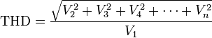
The quality of the inverter output waveform can be expressed by using the Fourier analysis data to calculate the total harmonic distortion (THD). The total harmonic distortion is the square root of the sum of the squares of the harmonic voltages divided by the fundamental voltage:
The quality of output waveform that is needed from an inverter depends on the characteristics of the connected load. Some loads need a nearly perfect sine wave voltage supply in order to work properly. Other loads may work quite well with a square wave voltage.
[edit] Advanced designs

There are many different power circuit topologies and control strategies used in inverter designs. Different design approaches address various issues that may be more or less important depending on the way that the inverter is intended to be used.
The issue of waveform quality can be addressed in many ways. Capacitors and inductors can be used to filter the waveform. If the design includes a transformer, filtering can be applied to the primary or the secondary side of the transformer or to both sides. Low-pass filters are applied to allow the fundamental component of the waveform to pass to the output while limiting the passage of the harmonic components. If the inverter is designed to provide power at a fixed frequency, a resonant filter can be used. For an adjustable frequency inverter, the filter must be tuned to a frequency that is above the maximum fundamental frequency.
Since most loads contain inductance, feedback rectifiers or antiparallel diodes are often connected across each semiconductor switch to provide a path for the peak inductive load current when the switch is turned off. The antiparallel diodes are somewhat similar to the freewheeling diodes used in AC/DC converter circuits.
Fourier analysis reveals that a waveform, like a square wave, that is antisymmetrical about the 180 degree point contains only odd harmonics, the 3rd, 5th, 7th etc. Waveforms that have steps of certain widths and heights eliminate or “cancel” additional harmonics. For example, by inserting a zero-voltage step between the positive and negative sections of the square-wave, all of the harmonics that are divisible by three can be eliminated. That leaves only the 5th, 7th, 11th, 13th etc. The required width of the steps is one third of the period for each of the positive and negative voltage steps and one sixth of the period for each of the zero-voltage steps.
Changing the square wave as described above is an example of pulse-width modulation (PWM). Modulating, or regulating the width of a square-wave pulse is often used as a method of regulating or adjusting an inverter's output voltage. When voltage control is not required, a fixed pulse width can be selected to reduce or eliminate selected harmonics. Harmonic elimination techniques are generally applied to the lowest harmonics because filtering is more effective at high frequencies than at low frequencies. Multiple pulse-width or carrier based PWM control schemes produce waveforms that are composed of many narrow pulses. The frequency represented by the number of narrow pulses per second is called the switching frequency or carrier frequency. These control schemes are often used in variable-frequency motor control inverters because they allow a wide range of output voltage and frequency adjustment while also improving the quality of the waveform.
Multilevel inverters provide another approach to harmonic cancellation. Multilevel inverters provide an output waveform that exhibits multiple steps at several voltage levels. For example, it is possible to produce a more sinusoidal wave by having split-rail direct current inputs at two voltages, or positive and negative inputs with a central ground. By connecting the inverter output terminals in sequence between the positive rail and ground, the positive rail and the negative rail, the ground rail and the negative rail, then both to the ground rail, a stepped waveform is generated at the inverter output. This is an example of a three level inverter: the two voltages and ground. [3]
[edit] Three phase inverters

Three-phase inverters are used for variable-frequency drive applications and for high power applications such as HVDC power transmission. A basic three-phase inverter consists of three single-phase inverter switches each connected to one of the three load terminals. For the most basic control scheme, the operation of the three switches is coordinated so that one switch operates at each 60 degree point of the fundamental output waveform. This creates a line-to-line output waveform that has six steps. The six-step waveform has a zero-voltage step between the positive and negative sections of the square-wave such that the harmonics that are multiples of three are eliminated as described above. When carrier-based PWM techniques are applied to six-step waveforms, the basic overall shape, or envelope, of the waveform is retained so that the 3rd harmonic and its multiples are cancelled.

To construct inverters with higher power ratings, two six-step three-phase inverters can be connected in parallel for a higher current rating or in series for a higher voltage rating. In either case, the output waveforms are phase shifted to obtain a 12-step waveform. If additional inverters are combined, an 18-step inverter is obtained with three inverters etc. Although inverters are usually combined for the purpose of achieving increased voltage or current ratings, the quality of the waveform is improved as well.
[edit] History
[edit] Early inverters
From the late nineteenth century through the middle of the twentieth century, DC-to-AC power conversion was accomplished using rotary converters or motor-generator sets (M-G sets). In the early twentieth century, vacuum tubes and gas filled tubes began to be used as switches in inverter circuits. The most widely used type of tube was the thyratron.
The origins of electromechanical inverters explain the source of the term inverter. Early AC-to-DC converters used an induction or synchronous AC motor direct-connected to a generator (dynamo) so that the generator's commutator reversed its connections at exactly the right moments to produce DC. A later development is the synchronous converter, in which the motor and generator windings are combined into one armature, with slip rings at one end and a commutator at the other and only one field frame. The result with either is AC-in, DC-out. With an M-G set, the DC can be considered to be separately generated from the AC; with a synchronous converter, in a certain sense it can be considered to be "mechanically rectified AC". Given the right auxiliary and control equipment, an M-G set or rotary converter can be "run backwards", converting DC to AC. Hence an inverter is an inverted converter.[4][5]
[edit] Controlled rectifier inverters
Since early transistors were not available with sufficient voltage and current ratings for most inverter applications, it was the 1957 introduction of the thyristor or silicon-controlled rectifier (SCR) that initiated the transition to solid state inverter circuits.

The commutation requirements of SCRs are a key consideration in SCR circuit designs. SCRs do not turn off or commutate automatically when the gate control signal is shut off. They only turn off when the forward current is reduced to zero through some external process. For SCRs connected to an AC power source, commutation occurs naturally every time the polarity of the source voltage reverses. SCRs connected to a DC power source usually require a means of forced commutation that forces the current to zero when commutation is required. The least complicated SCR circuits employ natural commutation rather than forced commutation. With the addition of forced commutation circuits, SCRs have been used in the types of inverter circuits described above.
In applications where inverters transfer power from a DC power source to an AC power source, it is possible to use AC-to-DC controlled rectifier circuits operating in the inversion mode. In the inversion mode, a controlled rectifier circuit operates as a line commutated inverter. This type of operation can be used in HVDC power transmission systems and in regenerative braking operation of motor control systems.
Another type of SCR inverter circuit is the current source input (CSI) inverter. A CSI inverter is the dual of a six-step voltage source inverter. With a current source inverter, the DC power supply is configured as a current source rather than a voltage source. The inverter SCRs are switched in a six-step sequence to direct the current to a three-phase AC load as a stepped current waveform. CSI inverter commutation methods include load commutation and parallel capacitor commutation. With both methods, the input current regulation assists the commutation. With load commutation, the load is a synchronous motor operated at a leading power factor.
As they have become available in higher voltage and current ratings, semiconductors such as transistors that can be turned off by means of control signals have become the preferred switching components for use in inverter circuits.
[edit] Rectifier and inverter pulse numbers
Rectifier circuits are often classified by the number of current pulses that flow to the DC side of the rectifier per cycle of AC input voltage. A single-phase half-wave rectifier is a one-pulse circuit and a single-phase full-wave rectifier is a two-pulse circuit. A three-phase half-wave rectifier is a three-pulse circuit and a three-phase full-wave rectifier is a six-pulse circuit.[6]
With three-phase rectifiers, two or more rectifiers are sometimes connected in series or parallel to obtain higher voltage or current ratings. The rectifier inputs are supplied from special transformers that provide phase shifted outputs. This has the effect of phase multiplication. Six phases are obtained from two transformers, twelve phases from three transformers and so on. The associated rectifier circuits are 12-pulse rectifiers, 18-pulse rectifiers and so on.
When controlled rectifier circuits are operated in the inversion mode, they would be classified by pulse number also. Rectifier circuits that have a higher pulse number have reduced harmonic content in the AC input current and reduced ripple in the DC output voltage. In the inversion mode, circuits that have a higher pulse number have lower harmonic content in the AC output voltage waveform.
[edit] See also
- Solar inverter
- Grid tie inverter
- Push-pull converter
- Variable-frequency drive
- Static inverter plant
- Switched-mode power supply (SMPS)
- Pacific Intertie HVDC power transmission line
- Space vector modulation
[edit] References
[edit] Citations
- ^ http://www.greentechmedia.com/articles/enphase-raises-15m-for-micro-inverters-1373.html
- ^ "Power Electronics: Energy Manager for Hybrid Electric Vehicles". Oak Ridge National Laboratory Review (U.S. Department of Energy) 33 (3). 2000. http://www.ornl.gov/info/ornlreview/v33_3_00/power.htm. Retrieved on 2006-11-08.
- ^ Rodriguez, Jose; et al. (August 2002). "Multilevel Inverters: A Survey of Topologies, Controls, and Applications". IEEE Transactions on Industrial Electronics (IEEE) 49 (4): 724–738. doi:.
- ^ "Inverter FAQ". PowerStream. 2006. http://www.powerstream.com/inFAQ.htm. Retrieved on 2006-11-08.
- ^ Owen, Edward L. (January/February 1996). "Origins of the Inverter". IEEE Industry Applications Magazine: History Department (IEEE) 2 (1): 64–66. doi:.
- ^ D. R. Grafham and J. C. Hey, editors, ed. SCR Manual (Fifth Edition ed.). Syracuse, N.Y. USA: General Electric. pp. 236–239.
[edit] General references
- Bedford, B. D.; Hoft, R. G. et al (1964). Principles of Inverter Circuits. New York: John Wiley & Sons, Inc.. ISBN 0-471-06134-4.
- Mazda, F. F. (1973). Thyristor Control. New York: Halsted Press Div. of John Wiley & Sons. ISBN 0-470-58116-6.
[edit] External links
- Solar Panel Inverters explained in great detail.
- Sine Wave Versus Modified Sine Wave Power Inverter Video
- EFN.cn inverter manufacturer list: 170 companies with inverter power ranges, types, and contact information
- Virtual Synchronous Machine

