Anechoic chamber
From Wikipedia, the free encyclopedia
|
|
This article may require cleanup to meet Wikipedia's quality standards. Please improve this article if you can. (January 2008) |
|
|
This article is missing citations or needs footnotes. Please help add inline citations to guard against copyright violations and factual inaccuracies. (January 2008) |
|
|
This article may contain original research or unverified claims. Please improve the article by adding references. See the talk page for details. (January 2008) |
An anechoic chamber is a shielded room designed to attenuate sound or electromagnetic energy. Anechoic chambers were originally used in the context of absorbing acoustic (sound) echoes caused by internal reflections of a room, but more recently anechoic chambers have also been used to provide a shielded environment for radio frequency (RF) and microwaves.
An RF anechoic chamber is designed to suppress the electromagnetic wave energy of echoes: reflected electromagnetic waves, from the internal surfaces. Both types of chamber are constructed with echo suppression features and with effective isolation from the acoustic or RF noise present in the external environment. In a well-designed acoustic or RF anechoic chamber, the equipment under test receives acoustic, mechanical or RF signals from a signal source, a perfect chamber will not internally reflect these transmitted waves. This ensures the integrity of the subject being tested is not influenced by external or internal reflected noise. Furthermore, the shielding of the chamber limits interference from equipment located outside of the chamber.
Anechoic chambers range from small compartments to chambers as large as aircraft hangars. The size of an anechoic chamber depends on the size of the objects to be tested and the frequency range of the radio or microwave signals used. Radio frequency interference (RFI) is the unwanted reception of radio signals. Radio frequency interference sources include lightning, electrical equipment, fluorescent lighting, cell phones, and transmitting equipment from radio stations. RFI testing helps determine which frequencies affect particular electronic systems and provide clues to mitigating the risks to communication devices or developing measures to counter the interference.
Contents |
[edit] Acoustic anechoic chambers
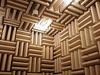
Anechoic chambers are commonly used in acoustics to conduct experiments in nominally "free field" conditions. All sound energy will be traveling away from the source with almost none reflected back. Common anechoic chamber experiments include measuring the transfer function of a loudspeaker or the directivity of noise radiation from industrial machinery. In general, the interior of an anechoic chamber is very quiet, with typical noise levels in the 10-20 dBA range. According to Guinness World Records, 2005, Orfield Laboratory's NIST certified anechoic chamber is "The quietest place on earth" measured at -9.4 dBA. [1]The human ear can typically detect sounds above 0 dB, so a human in such a chamber would perceive the surroundings as void of sound.
[edit] Semi-anechoic chambers
Full anechoic chambers aim to absorb energy in all directions. Semi-anechoic chambers have a solid floor that acts as a work surface for supporting heavy items, such as cars, washing machines, or industrial machinery, rather than the mesh floor grille found over absorbent tiles present in full anechoic chambers. This floor is damped and floating on absorbent buffers to isolate it from outside vibration or electromagnetic signals. Recording artists recording studio may utilize the semi-anechoic chamber to produce high-quality music free of outside noise and unwanted echoes.
[edit] Radio-frequency anechoic chambers

The internal appearance of the radio frequency (RF) anechoic chamber is sometimes similar to that of an acoustic anechoic chamber, however, the interior surfaces of the RF anechoic chamber are covered with radiation absorbent material (RAM) instead of acoustically absorbent material [1]. The RF anechoic chamber is typically used to house the equipment for performing measurements of antenna radiation patterns, electromagnetic compatibility (EMC) and radar cross section measurements. Testing can be conducted on full-scale objects, including aircraft, or on scale models where the wavelength of the measuring radiation is scaled in direct proportion to the target size. Coincidentally, many RF anechoic chambers which use pyramidal RAM also exhibit some of the properties of an acoustic anechoic chamber, such as attenuation of sound and shielding from outside noise.
[edit] Radiation absorbent material
The RAM is designed and shaped to absorb incident RF radiation (also known as non-ionising radiation), as effectively as possible, from as many incident directions as possible. The more effective the RAM is the less will be the level of reflected RF radiation. Many measurements in electromagnetic compatibility (EMC) and antenna radiation patterns require that spurious signals arising from the test setup, including reflections, are negligible to avoid the risk of causing measurement errors and ambiguities.
One of the most effective types of RAM comprises arrays of pyramid shaped pieces, each of which is constructed from a suitably lossy material. To work effectively, all internal surfaces of the anechoic chamber must be entirely covered with RAM. Sections of RAM may be temporarily removed to install equipment but they must be replaced before performing any tests. To be sufficiently lossy, RAM can neither be a good electrical conductor nor a good electrical insulator as neither type actually absorbs any power. It has to be an intermediate grade of material which absorbs power gradually in a controlled way as the incident wave penetrates it. Typically pyramidal RAM will comprise a rubberized foam material impregnated with controlled mixtures of carbon and iron.
An alternative type of RAM comprises flat plates of ferrite material, in the form of flat tiles fixed to all interior surfaces of the chamber. This type has a smaller effective frequency range than the pyramidal RAM and is designed to be fixed to good conductive surfaces. It is generally easier to fit and more durable than the pyramidal type RAM but is less effective at higher frequencies. Its performance might however be quite adequate if tests are limited to lower frequencies (ferrite plates have a damping curve that makes them most effective between 30-1000MHz)[2].
There is also a hybrid type, a ferrite in pyramidal shape. Containing the advantages of both technologies the frequency range can be maximized while the pyramid remains small (10cm)[3].
[edit] Effectiveness over frequency

Waves of higher frequencies have smaller amplitudes and are higher in energy, while waves of lower frequencies have larger amplitudes and are lower in energy, according to the relationship λ = v / f where lambda represents wavelength, v is phase velocity of wave, and f is frequency. To shield for a specific wavelength, the cone must be of appropriate size to absorb that wavelength. The performance quality of an RF anechoic chamber is determined by its lowest test frequency of operation, at which measured reflections from the internal surfaces will be the most significant compared to higher frequencies. Pyramidal RAM is at its most absorptive when the incident wave is at normal incidence to the internal chamber surface when the pyramid height is approximately equal to λ / 4, where λ is the free space wavelength. Accordingly, increasing the pyramid height of the RAM for the same (square) base size improves the effectiveness of the chamber at low frequencies but results in increased cost and a reduced unobstructed working volume that is available inside a chamber of defined size.
[edit] Installation into a screened room
An RF anechoic chamber is usually built into a screened room, designed using the Faraday cage principle. This is because most of the RF tests that require an anechoic chamber to minimize reflections from the inner surfaces also require the properties of a screened room to attenuate unwanted signals penetrating inwards and causing interference to the equipment under test and prevent leakage from tests penetrating outside.
[edit] Chamber size and commissioning
The actual test setups usually require extra room than that required to simply house the test equipment, the hardware under test and associated cables. For example, the far field criteria sets a minimum distance between the transmitting antenna and the receiving antenna to be observed when measuring antenna radiation patterns. Allowing for this and the extra space that may be required for the pyramidal RAM means that a substantial capital investment is required into even a modestly dimensioned chamber. For most companies a such an investment in a large RF anechoic chamber is not justifiable unless it is likely to be used continuously or perhaps rented out. Sometimes for radar cross section measurements it is possible to scale down the objects under test and reduce the chamber size provided that the wavelength of the test frequency is scaled down in direct proportion.
RF anechoic chambers are normally designed to meet the electrical requirements of one or more accredited standards. For example, the aircraft industry may test equipment for aircraft according to company specifications or military specifications such as MIL-STD 461E. Once built, acceptance tests are performed during commissioning to verify that the standard(s) are in fact met. Provided they are, a certificate will be issued to that effect, valid for a limited period.
[edit] Operational use
Test and supporting equipment configurations to be used within anechoic chambers must expose as few metallic (conductive) surfaces as possible, as these risk causing unwanted reflections. Often this is achieved by using non-conductive plastic or wooden structures for supporting the equipment under test. Where metallic surfaces are unavoidable, they may be covered with pieces of RAM after setting up to minimize such reflection as far as possible.
A careful assessment of whether to place the test equipment (as opposed to the equipment under test) on the interior or exterior of the chamber is required. Normally this may be located outside of the chamber provided it is not susceptible to interference from exterior fields which, otherwise, would not be present inside the chamber. This has the advantage of reducing reflection surfaces inside but it requires extra cables and particularly good filtering. Unnecessary cables and/or poor filtering can collect interference on the outside and conduct them to the inside. A good compromise may be to install human interface equipment (such as PCs), electrically noisy and high power equipment on the outside and sensitive equipment on the inside.
One useful application of fiber optic cables is to provide the communications links to carry signals within the chamber. Fiber optic cables are non-conductive and of small cross-section and therefore cause negligible reflections in most applications.
It is normal to filter electrical power supplies for use within the anechoic chamber as unfiltered supplies present a risk of unwanted signals being conducted into and out of the chamber along the power cables.
[edit] Health and safety risks associated with RF anechoic chamber
The following health and safety risks are associated with RF anechoic chambers:
- RF radiation hazard
- Fire hazard
- Trapped personnel
Personnel are not normally permitted inside the chamber during a measurement as this not only can cause unwanted reflections from the human body but may also be a radiation hazard to the personnel concerned if tests are being performed at high RF powers. Such risks are from RF or non-ionizing radiation and not from the higher energy ionizing radiation.
As RAM is highly absorptive of RF radiation, incident radiation will generate heat within the RAM. If this cannot be dissipated adequately there is a risk that hot spots may develop and the RAM temperature may rise to the point of combustion. This can be a risk if a transmitting antenna inadvertently gets too close to the RAM. Even for quite modest transmitting power levels, high gain antennas can concentrate the power sufficiently to cause high power flux near their apertures. Although recently manufactured RAM is normally treated with a fire retardant to reduce such risks, they are difficult to completely eliminate.
Safety regulations normally require the installation of a gaseous fire suppression system including smoke detectors. Gaseous fire suppression avoids damage caused by the extinguishing agent which would otherwise worsen damage caused by the fire itself. A common gaseous fire suppression agent is carbon dioxide. Normally the fire detection system is linked into the power supply to the chamber, so that the fire detection system can disconnect the power supply if smoke or a fire is detected.
[edit] References
|
|
This article does not cite any references or sources. Please help improve this article by adding citations to reliable sources (ideally, using inline citations). Unsourced material may be challenged and removed. (April 2008) |
[edit] External links
| Wikimedia Commons has media related to: Shielding rooms |

