Chroma subsampling
From Wikipedia, the free encyclopedia
|
|
This article needs additional citations for verification. Please help improve this article by adding reliable references (ideally, using inline citations). Unsourced material may be challenged and removed. (August 2008) |
Chroma subsampling is the practice of encoding images by implementing less resolution for chroma information than for luma information. It is used in many video encoding schemes — both analog and digital — and also in JPEG encoding.
Contents |
[edit] Rationale
Because of storage and transmission limitations, there is always a desire to reduce (or compress) the signal. Since the human visual system is much more sensitive to variations in brightness than color, a video system can be optimized by devoting more bandwidth to the luma component (usually denoted Y'), than to the color difference components Cb and Cr. The 4:2:2 Y'CbCr scheme for example requires two-thirds the bandwidth of (4:4:4) R'G'B'. This reduction results in almost no visual difference as perceived by the viewer.
[edit] How subsampling works
Because the human visual system is less sensitive to the position and motion of color than luminance,[1] bandwidth can be optimized by storing more luminance detail than color detail. At normal viewing distances, there is no perceptible loss incurred by sampling the color detail at a lower rate. In video systems, this is achieved through the use of color difference components. The signal is divided into a luma (Y') component and two color difference components (chroma).
Chroma subsampling deviates from color science in that the luma and chroma components are formed as a weighted sum of gamma-corrected (tristimulus) R'G'B' components instead of linear (tristimulus) RGB components. As a result, luminance and color detail are not completely independent of one another. There is some "bleeding" of luminance and color information between the luma and chroma components. The error is greatest for highly-saturated colors and can be somewhat noticeable in between the magenta and green bars of a color bars test pattern (that has chroma subsampling applied). This engineering approximation (by reversing the order of operations between gamma correction and forming the weighted sum) allows color subsampling to be more easily implemented.

Original without color subsampling. 200% zoom.

Image after color subsampling (compressed with Sony Vegas DV codec, box filtering applied.)
|
|
This article's factual accuracy is disputed. Please see the relevant discussion on the talk page. (September 2008) |
[edit] Sampling systems and ratios
The subsampling scheme is commonly expressed as a three part ratio J:a:b (e.g. 4:2:2), although sometimes expressed as four parts (e.g. 4:2:2:4), that describe the number of luminance and chrominance samples in a conceptual region that is J pixels wide, and 2 pixels high. The parts are (in their respective order):
- J horizontal sampling reference (width of the conceptual region). Usually, 4.
- a number of chrominance samples (Cr, Cb) in the first row of J pixels.
- b number of (additional) chrominance samples (Cr, Cb) in the second row of J pixels.
- Alpha horizontal factor (relative to first digit). May be omitted if alpha component is not present, and is equal to J when present.
An explanatory image of different chroma subsampling schemes can be seen at the following link: http://lea.hamradio.si/~s51kq/subsample.gif (source: "Basics of Video": http://lea.hamradio.si/~s51kq/V-BAS.HTM) or in details in Chrominance Subsampling in Digital Images.
To calculate required bandwidth factor relative to 4:4:4 (or 4:4:4:4), one needs to sum all the factors and divide the result by 12 (or 16, if alpha is present).
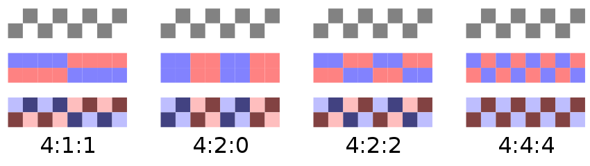
The mapping examples given are only theoretical and for illustration. Also note that the diagram does not indicate any chroma filtering, which should be applied to avoid aliasing.
[edit] Types of subsampling
[edit] 8:4:4 Y'CbCr
Each of the two Chroma, Cb Cr, components have the same sample rate. The Luminance has twice the resolution as Chroma components. This scheme is sometimes used in high-end Film scanners, DataCine, telecine and color grading. In NTSC this would be about 10 MHz Luma and 5 MHz chroma resolution, (as compared to 4:4:4: in which all three would have 5 MHz resolution.) Two links (connections) are required to carry this bandwidth. These links are often referred to as Link A and Link B. Each link would carry a 4:2:2 signal, when combined these would make 8:4:4. A down sample converter could later convert 8:4:4 to 4:4:4 or 4:2:2.
[edit] 4:4:4 Y'CbCr
Each of the three Y'CbCr components have the same sample rate. This scheme is sometimes used in high-end film scanners and cinematic postproduction. Two links (connections) are normally required to carry this bandwidth: Link A would carry a 4:2:2 signal, Link B a 0:2:2, when combined would make 4:4:4.
[edit] 4:4:4 R'G'B' (no subsampling)
Note that "4:4:4" may instead be referring to R'G'B' color space, which implicitly does not have any chroma subsampling at all. Formats such as HDCAM SR can record 4:4:4 R'G'B' over dual-link HD-SDI.
[edit] 4:2:2
The two chroma components are sampled at half the sample rate of luma: the horizontal chroma resolution is halved. This reduces the bandwidth of a video signal by one-third with little to no visual difference.
Many high-end digital video formats and interfaces use this scheme:
- AVC-Intra 100
- Digital Betacam
- DVCPRO50 and DVCPRO HD
- Digital-S
- CCIR 601 / Serial Digital Interface / D1
- ProRes 422
- XDCAM HD422
[edit] 4:2:1
Although this mode is technically defined, very few software or hardware codecs use this sampling mode. Cb horizontal resolution is twice as low as one of Cr (and four times as low as one of Y). This exploits the fact that human eye is less sensitive to blue color than to red.
[edit] 4:1:1
In 4:1:1 chroma subsampling, the horizontal color resolution is quartered, and the bandwidth is halved compared to no chroma subsampling. Initially, 4:1:1 chroma subsampling of the DV format was not considered to be broadcast quality and was only acceptable for low-end and consumer applications.[2][3] Currently, DV-based formats (which use 4:1:1 chroma subsampling) are used professionally in electronic news gathering and in playout servers. DV has also been sporadically used in feature films and in digital cinematography.
Formats that use 4:1:1 chroma subsampling include:
[edit] 4:2:0
Different variants of 4:2:0 chroma configurations are found in:
- All versions of MPEG, including MPEG-2 implementations such as DVD (although some profiles of MPEG-4 allow higher-quality sampling schemes such as 4:4:4)
- PAL DV and DVCAM
- HDV
- AVCHD and AVC-Intra 50
- most common JPEG/JFIF, H.261, and MJPEG implementations
- VC-1
Cb and Cr are each subsampled at a factor of 2 both horizontally and vertically.
There are three variants of 4:2:0 schemes, having different horizontal and vertical siting. [4]
- In MPEG-2, Cb and Cr are cosited horizontally. Cb and Cr are sited between pixels in the vertical direction (sited interstitially).
- In JPEG/JFIF, H.261, and MPEG-1, Cb and Cr are sited interstitially, halfway between alternate luma samples.
- In 4:2:0 DV, Cb and Cr are cosited in the horizontal direction. In the vertical direction, they are cosited on alternating lines.
The PAL and SECAM color systems are especially well-suited to this kind of data reduction. Most digital video formats corresponding to PAL use 4:2:0 chroma subsampling, with the exception of DVCPRO25, which uses 4:1:1 chroma subsampling. Both the 4:1:1 and 4:2:0 schemes halve the bandwidth compared to no chroma subsampling.
With interlaced material, 4:2:0 chroma subsampling can result in motion artifacts if it is implemented the same way as for progressive material. The luma samples are derived from separate time intervals while the chroma samples would be derived from both time intervals. It is this difference that can result in motion artifacts. The MPEG-2 standard allows for an alternate interlaced sampling scheme where 4:2:0 is applied to each field (not both fields at once). This solves the problem of motion artifacts, reduces the vertical chroma resolution by half, and can introduce comb-like artifacts in the image.

Original. *This image shows a single field. The moving text has some motion blur applied to it.

4:2:0 progressive sampling applied to moving interlaced material. Note that the chroma leads and trails the moving text. *This image shows a single field.

4:2:0 interlaced sampling applied to moving interlaced material. *This image shows a single field.
In the 4:2:0 interlaced scheme however, vertical resolution of the chroma is roughly halved since the chroma samples effectively describe an area 2 samples wide by 4 samples tall instead of 2X2. As well, the spatial displacement between both fields can result in the appearance of comb-like chroma artifacts.

Original still image.

4:2:0 progressive sampling applied to a still image. Both fields are shown.

4:2:0 interlaced sampling applied to a still image. Both fields are shown.
If the interlaced material is to be de-interlaced, the comb-like chroma artifacts (from 4:2:0 interlaced sampling) can be removed by blurring the chroma vertically.[5]
[edit] 4:1:0
This ratio is possible, and some codecs support it, but it is not widely used. This ratio uses half of the vertical and one-fourth the horizontal color resolutions, with only one-eighth of the bandwidth of the maximum color resolutions used. Uncompressed video in this format with 8-bit quantization uses 10 bytes for every macropixel (which is 4 x 2 pixels). It has the equivalent chrominance bandwidth of a PAL I signal decoded with a delay line decoder, and still very much superior to NTSC.
- Some video codecs may operate at 4:1:0.5 or 4:1:0.25 as an option, so as to allow higher than VHS quality without having to take too large of a hit on bandwidth.
[edit] 3:1:1
Used by Sony in their HDCam High Definition recorders (not HDCAM SR).[citation needed] In the horizontal dimension, luma is sampled horizontally at three quarters of the full HD sampling rate- 1440 samples per row instead of 1920. Chroma is sampled at 480 samples per row, a third of the luma sampling rate.
In the vertical dimension, both luma and chroma are sampled at the full HD sampling rate (1080 samples vertically).
[edit] Out-of-gamut colors
One of the artifacts that can occur with chroma subsampling is that out-of-gamut colors can occur upon chroma reconstruction. Suppose the image consisted of alternating 1-pixel red and black lines. Chroma from the red pixels will be reconstructed onto the black pixels, causing the new pixels to have positive red and negative green and blue values. As displays cannot output negative light, these negative values will effectively be clipped and the resulting luma value will be too high.[6]
Filtering during subsampling can also cause colors to go out of gamut.
[edit] Terminology
The term Y'UV refers to an analog encoding scheme while Y'CbCr refers to a digital encoding scheme. One difference between the two is that the scale factors on the chroma components (U, V, Cb, and Cr) are different. However, the term YUV is often used erroneously to refer to Y'CbCr encoding. Hence, terms like "4:2:2 YUV" always refer to 4:2:2 Y'CbCr since there simply is no such thing as 4:x:x in analog encoding (such as YUV).
In a similar vein, the term luminance and the symbol Y are often used erroneously to refer to luma, which is denoted with the symbol Y'. Note that the luma (Y') of video engineering deviates from the luminance (Y) of color science (as defined by CIE). Luma is formed as the weighted sum of gamma-corrected (tristimulus) RGB components. Luminance is formed as a weighed sum of linear (tristimulus) RGB components.
In practice, the CIE symbol Y is often incorrectly used to denote luma. In 1993, SMPTE adopted Engineering Guideline EG 28, clarifying the two terms. Note that the prime symbol ' is used to indicate gamma correction.
Similarly, the chroma/chrominance of video engineering differs from the chrominance of color science. The chroma/chrominance of video engineering is formed from weighted tristimulus components, not linear components. In video engineering practice, the terms chroma, chrominance, and saturation are often used interchangeably to refer to chrominance.
[edit] See also
- Color space
- SMPTE - Society of Motion Picture and Television Engineers
- Digital video
- HDTV
- YCbCr
- YPbPr
- CCIR 601 4:2:2 SDTV
- YUV
- Color
- color vision
[edit] References
- ^ Livingstone, Margaret (2002). "The First Stages of Processing Color and Luminance: Where and What". Vision and Art: The Biology of Seeing. New York: Harry N. Abrams. pp. 46–67. ISBN 0-8109-0406-3.
- ^ Jennings, Roger; Bertel Schmitt (1997). "DV vs. Betacam SP". DV Central. http://www.dvcentral.org/DV-Beta.html. Retrieved on 2008-08-29.
- ^ Wilt, Adam J. (2006). "DV, DVCAM & DVCPRO Formats". adamwilt.com. http://www.adamwilt.com/DV-FAQ-tech.html. Retrieved on 2008-08-29.
- ^ Poynton, Charles (2008). "Chroma Subsampling Notation". Charles Poynton. http://www.poynton.com/PDFs/Chroma_subsampling_notation.pdf. Retrieved on 2008-10-01.
- ^ Munsil, Don; Stacey Spears (2003). "DVD Player Benchmark - Chroma Upsampling Error". Secrets of Home Theater & High Fidelity. http://www.hometheaterhifi.com/volume_8_2/dvd-benchmark-special-report-chroma-bug-4-2001.html. Retrieved on 2008-08-29.
- ^ Chan, Glenn. "Towards Better Chroma Subsampling". SMPTE Journal. http://www.glennchan.info/articles/technical/chroma/chroma1.htm. Retrieved on 2008-08-29.
- Poynton, Charles. "YUV and luminance considered harmful: A plea for precise terminology in video" [1]
- Poynton, Charles. "Digital Video and HDTV: Algorithms and Interfaces." USA: Morgan Kaufmann Publishers, 2003.
- Kerr, Douglas A. "Chrominance Subsampling in Digital Images" [2]
|
|||||||||||||||||||||||||||||||||||||||||||||||||||||||

