LED circuit
From Wikipedia, the free encyclopedia
|
|
This article may require cleanup to meet Wikipedia's quality standards. Please improve this article if you can. (December 2008) |

In electronics, the basic LED circuit is an electrical circuit used to power a light-emitting diode (LED). It consists of a voltage source powering two components connected in series: A current limiting resistor, and an LED. Optionally a switch may be introduced to open and close the circuit.[1] The switch may be replaced with another component or circuit to form a continuity tester[2]
The LED used will have a voltage drop specified at the intended operating current. Ohm's law and Kirchhoff's circuit laws are used to calculate the resistor that is used to attain the correct current.[3][4] The resistor value is computed by subtracting the LED voltage drop from the supply voltage, and then dividing by the desired LED operating current.[5]
This basic circuit is used in a wide range of applications, including many consumer appliances.[6]
Contents |
[edit] Simple Resistance formula for optimum brightness of the LED
The formula to use to calculate the correct resistance to use is:

where:
- Power supply voltage (Vs) is the voltage of the power supply e.g. a 9 volt battery.
- LED voltage drop (Vf) is the voltage drop across the LED (typically about 1.8 - 3.3 volts; this varies by the color of the LED) 1.8v for RED and its gets higher as the spectrum inceases to 3.3volts for BLUE.
- LED current rating (If) is the manufacturer rating of the LED (usually given in milliamperes such as 20mA)
[edit] Analysis using Kirchoff's Laws
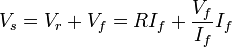
The formula can be explained considering the LED as a  resistance, and applying the KVL (R is the unknown quantity):


[edit] See also
- Ohm's law
- Kirchhoff's circuit laws
- LED Limiting Resistor Calculator [1]
[edit] References
- ^ Singmin, Andrew (1997). "3. Building a Project Using a Basic LED Circuit". Beginning electronics through projects. Oxford [England]: Newnes. p. 29. ISBN 0-7506-9898-5. "As you can see in Figure 3-1, there are just four components in an LED circuit. They are • a battery, • a switch, • an LED, and • a resistor."
- ^ Cave, John; Caborn, Colin; Mould, Ian (2000). Design and Technology. Cheltenham: Nelson Thornes Ltd. p. 116. ISBN 0-17-448277-9. "A fuse or filament bulb placed to complete the circuit will show whether the bulb or fuse is good."
- ^ Meade, Russell L. (2004). Foundations of Electronics: Circuits & Devices Conventional Flow. Clifton Park, NY: Thomson Delmar Learning. p. 1051. ISBN 1-4018-5976-3. "The value of the current limiting resistor connected in series with the LED depends on the amount of supply voltage."
- ^ applied electronics - Page 270
- ^ Walsh, Ronald A. (2000). Electromechanical design handbook. New York: McGraw-Hill. pp. 6–242. ISBN 0-07-134812-3. "The light-emitting diode is normally fed from a supply voltage source that is higher than the LED can sustain without burnout."
- ^ Catsoulis, John (2003). Designing embedded hardware. Sebastopol, CA: O'Reilly. ISBN 0-596-00362-5. "This simple LED circuit (or variations of it) drives the LEDs on your PC's front panel, your VCR and DVD player, your cell phone, and a host of other appliances."

