Potentiometer
From Wikipedia, the free encyclopedia
| Potentiometer | |
 A typical single turn potentiometer |
|
| Type | Passive |
|---|---|
| Electronic symbol | |
A potentiometer is a three-terminal resistor with a sliding contact that forms an adjustable voltage divider.[1] If only two terminals are used (one side and the wiper), it acts as a variable resistor or Rheostat. Potentiometers are commonly used to control electrical devices such as a volume control of a radio. Potentiometers operated by a mechanism can be used as position transducers, for example, in a joystick.

Potentiometers are rarely used to directly control significant power (more than a watt). Instead they are used to adjust the level of analog signals (e.g. volume controls on audio equipment), and as control inputs for electronic circuits. For example, a light dimmer uses a potentiometer to control the switching of a TRIAC and so indirectly control the brightness of lamps.
Potentiometers are sometimes provided with one or more switches mounted on the same shaft. For instance, when attached to a volume control, the knob can also function as an on/off switch at the lowest volume.
Contents |
[edit] Construction of potentiometers
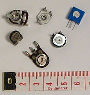
A potentiometer (colloquially called a "pot") is constructed using a semi-circular resistive element with a sliding contact (wiper). The resistive element, with a terminal at one or both ends, is flat or angled, and is commonly made of graphite, although other materials may be used instead. The wiper is connected through another sliding contact to another terminal. On panel pots, the wiper is usually the center terminal of three. For single-turn pots, this wiper typically travels just under one revolution around the contact. "Multiturn" potentiometers also exist, where the resistor element may be helical and the wiper may move 10, 20, or more complete revolutions, though multiturn pots are usually constructed of a conventional resistive element wiped via a worm gear. Besides graphite, materials used to make the resistive element include resistance wire, carbon particles in plastic, and a ceramic/metal mixture called cermet.
One form of rotary potentiometer is called a String potentiometer. It is a multi-turn potentiometer operated by an attached reel of wire turning against a spring. It is used as a position transducer.
In a linear slider pot, a sliding control is provided instead of a dial control. The resistive element is a rectangular strip, not semi-circular as in a rotary potentiometer. Because of the large opening for the wiper and knob, this type of pot has a greater potential for getting contaminated.
Potentiometers can be obtained with either linear or logarithmic relations between the slider position and the resistance (potentiometer laws or "tapers").
Manufacturers of conductive track potentiometers use conductive polymer resistor pastes that contain hard wearing resins and polymers, solvents, lubricant and carbon – the constituent that provides the conductive/resistive properties. The tracks are made by screen printing the paste onto a paper based phenolic substrate and then curing it in an oven. The curing process removes all solvents and allows the conductive polymer to polymerize and cross link. This produces a durable track with stable electrical resistance throughout its working life.[citation needed]
[edit] Linear taper potentiometer
A linear taper potentiometer has a resistive element of constant cross-section, resulting in a device where the resistance between the contact (wiper) and one end terminal is proportional to the distance between them. Linear taper describes the electrical characteristic of the device, not the geometry of the resistive element. Linear taper potentiometers are used when an approximately proportional relation is desired between shaft rotation and the division ratio of the potentiometer; for example, controls used for adjusting the centering of (an analog) cathode-ray oscilloscope.
[edit] Logarithmic potentiometer
A logarithmic taper potentiometer has a resistive element that either 'tapers' in from one end to the other, or is made from a material whose resistivity varies from one end to the other. This results in a device where output voltage is a logarithmic (or inverse logarithmic depending on type) function of the mechanical angle of the pot.
Most (cheaper) "log" pots are actually not logarithmic, but use two regions of different, but constant, resistivity to approximate a logarithmic law. A log pot can also be simulated with a linear pot and an external resistor. True log pots are significantly more expensive.
Logarithmic taper potentiometers are often used in connection with audio amplifiers.
[edit] Rheostat
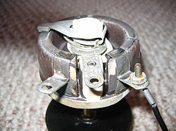
A rheostat is a two-terminal variable resistor. Often these are designed to handle much higher voltage and current. Typically these are constructed as a resistive wire wrapped to form a toroid coil with the wiper moving over the upper surface of the toroid, sliding from one turn of the wire to the next. Sometimes a rheostat is made from resistance wire wound on a heat resisting cylinder with the slider made from a number of metal fingers that grip lightly onto a small portion of the turns of resistance wire. The 'fingers' can be moved along the coil of resistance wire by a sliding knob thus changing the 'tapping' point. They are usually used as variable resistors rather than variable potential dividers.
Any three-terminal potentiometer can be used as a two-terminal variable resistor, by not connecting to the third terminal. It is common practice to connect the wiper terminal to the unused end of the resistance track to reduce the amount of resistance variation caused by dirt on the track.
[edit] Digital Potentiometer
A digital potentiometer is an electronic component that mimics the functions of analog potentiometers. Through digital input signals, the resistance between two terminals can be adjusted, just as in an analog potentiometer.
[edit] Applications of potentiometers
Potentiometers are widely used as user controls, and may control a very wide variety of equipment functions. The widespread use of potentiometers in consumer electronics has declined in the 1990s, with digital controls now more common. However they remain in many applications, such as volume controls and as position sensors.
[edit] Audio control

One of the most common uses for modern low-power potentiometers is as audio control devices. Both sliding pots (also known as faders) and rotary potentiometers (commonly called knobs) are regularly used to adjust loudness, frequency attenuation and other characteristics of audio signals.
The 'log pot' is used as the volume control in audio amplifiers, where it is also called an "audio taper pot", because the amplitude response of the human ear is also logarithmic. It ensures that, on a volume control marked 0 to 10, for example, a setting of 5 sounds half as loud as a setting of 10. There is also an anti-log pot or reverse audio taper which is simply the reverse of a log pot. It is almost always used in a ganged configuration with a log pot, for instance, in an audio balance control.
Potentiometers used in combination with filter networks act as tone controls or equalizers.
[edit] Television
Potentiometers were formerly used to control picture brightness, contrast, and (in NTSC receivers) color response. A potentiometer was often used to adjust "vertical hold", which affected the synchronization between the receiver's internal sweep circuit (sometimes a multivibrator) and the received picture signal.
[edit] Transducers
Potentiometers are also very widely used as a part of displacement transducers because of the simplicity of construction and because they can give a large output signal.
[edit] Computation
In analog computers, potentiometers are used to scale intermediate results by desired constant factors, or to set initial conditions for a calculation. A motor-driven potentiometer may be used as a function generator, using a non-linear resistance card to supply approximations to trigonometric functions. For example, the shaft rotation might represent an angle, and the voltage division ratio can be made proportional to the cosine of the angle.
[edit] Theory of operation

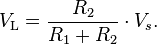
The potentiometer can be used as a voltage divider to obtain a manually adjustable output voltage at the slider (wiper) from a fixed input voltage applied across the two ends of the pot. This is the most common use of pots.
The voltage across RL can be calculated by:

If RL is large compared to the other resistances (like the input to an operational amplifier), the output voltage can be approximated by the simpler equation:
As an example, assume
 ,
,  ,
,  , and
, and 
Since the load resistance is large compared to the other resistances, the output voltage VL will be approximately:

Due to the load resistance, however, it will actually be slightly lower: ≈ 6.623 V.
One of the advantages of the potential divider compared to a variable resistor in series with the source is that, while variable resistors have a maximum resistance where some current will always flow, dividers are able to vary the output voltage from maximum (VS) to ground (zero volts) as the wiper moves from one end of the pot to the other. There is, however, always a small amount of contact resistance.
In addition, the load resistance is often not known and therefore simply placing a variable resistor in series with the load could have a negligible effect or an excessive effect, depending on the load.
[edit] Early patents
- Coiled resistance wire rheostat, US patent 131,334, Thomas Edison, 1872
- Mary Hallock-Greenewalt invented a type of nonlinear rheostat for use in her visual-music instrument the Sarabet (US Patent 1,357,773, 1920)
[edit] See also
- Potentiometric sensor
- Digital Potentiometer
- Determining emf of primary cells using potentiometer
- Trimmer
- Potentiometer (measuring instrument)
[edit] References
- ^ The Authoritative Dictionary of IEEE Standards Terms (IEEE 100) (seventh edition ed.). Piscataway, New Jersey: IEEE Press. 2000. ISBN 0-7381-2601-2.
[edit] External links
- Rheostat - Interactive Java Tutorial National High Magnetic Field Laboratory
- Information on a Variety of Commercial and Military grade Potentiometers: Which Is Right for My Application?
- Pictures of measuring potentiometers
- Electrical calibration equipment including various measurement potentiometers
- The Secret Life of Pots - Dissecting and repairing potentiometers
- Beginners' Guide to Potentiometers
- Making a rheostat
- Linear pot turned into log pot
- Potentiometer calculations as voltage divider - loaded and open circuit (unloaded)
- Application of Intersil Digitally Controlled Potentiometers (XDCP) as Hybrid Analog/Digital Feedback System Control Elements
- DACs vs. Digital Potentiometers: Which Is Right for My Application?
- Wirewound and Non-wirewound Precision Potentiometers Industry Standard
- Potentiometer-Based Position Transducer Voltage Divider Calculator

