Fluorescent lamp
From Wikipedia, the free encyclopedia


A fluorescent lamp or fluorescent tube is a gas-discharge lamp that uses electricity to excite mercury vapor. The excited mercury atoms produce short-wave ultraviolet light that then causes a phosphor to fluoresce, producing visible light.
Unlike incandescent lamps, fluorescent lamps always require a ballast to regulate the flow of power through the lamp. However, a fluorescent lamp converts electrical power into useful light more efficiently than an incandescent lamp; lower energy costs offsets the higher initial cost of the lamp. While larger fluorescent lamps have been mostly used in large commercial or institutional buildings, the compact fluorescent lamp is now being used as an energy-saving alternative to incandescent lamps in homes. Compared with incandescent lamps, fluorescent lamps use less power for the same amount of light, generally last longer, but are bulkier, more complex, and more expensive than a comparable incandescent lamp.
Contents |
[edit] History
|
|
This article may require cleanup to meet Wikipedia's quality standards. Please improve this article if you can. (February 2008) |
[edit] Physical discoveries
The history of the fluorescent lamp begins with early research into electrical phenomena. By the beginning of the 18th century, experimenters had observed a radiant glow emanating from partially evacuated glass vessels through which an electrical current passed. Little more could be done with this phenomenon until 1856 when a German glassblower named Heinrich Geissler (1815–1879) created a mercury vacuum pump that evacuated a glass tube to an extent not previously possible. When an electrical current passed through a Geissler tube, a strong green glow on the walls of the tube at the cathode end could be observed.
Because it produced some beautiful light effects, the Geissler tube was a popular source of amusement. More important, however, was its contribution to scientific research. One of the first scientists to experiment with a Geissler tube was Julius Plücker (1801–1868) who systematically described in 1858 the luminescent effects that occurred in a Geissler tube. He also made the important observation that the glow in the tube shifted position when in proximity to an electromagnetic field.
Inquiries that began with the Geissler tube continued as even better vacuums were produced. The most famous was the evacuated tube used for scientific research by William Crookes (1832–1919). That tube was evacuated by the highly effective mercury vacuum pump created by Hermann Sprengel (1834–1906). Research conducted by Crookes and others ultimately led to the discovery of the electron in 1897 by J. J. Thomson (1856–1940). But the Crookes tube, as it came to be known, produced little light because the vacuum in it was too good and thus lacked the trace amounts of gas that are needed for electrically stimulated luminescence.
Alexandre Edmond Becquerel observed in 1859 that certain substances gave off light when they were placed in a Geissler tube. He went on to apply thin coatings of luminescent materials to the surfaces of these tubes. Fluorescence occurred, but the tubes were very inefficient and had a short operating life. A few years earlier another scientist, George G. Stokes (1819–1903), had noted that ultraviolet light caused fluorspar to fluoresce, a property that would become critically important for the development of fluorescent lights many decades later.
[edit] Early discharge lamps
While Becquerel was primarily interested in conducting scientific research into fluorescence, Thomas Edison (1847–1931) briefly pursued fluorescent lighting for its commercial potential. He invented a fluorescent lamp in 1896 which used a coating of calcium tungstate as the fluorescing substance, excited by X-rays, but although it received a patent in 1907[1], it was not put into production. As with a few other attempts to use Geissler tubes for illumination, it had a short operating life, and given the success of the incandescent light, Edison had little reason to pursue an alternative means of electrical illumination. Nikola Tesla made similar experiments in the 1890s, devising high frequency powered fluorescent bulbs that gave a bright greenish light, but as with Edison's devices, no commercial success was achieved.
Although Edison lost interest in fluorescent lighting, one of his former employees was able to create a gas-based lamp that achieved a measure of commercial success. In 1895 Daniel McFarlan Moore (1869–1933) demonstrated lamps 2 to 3 m (7 to 9 feet) in length that used carbon dioxide or nitrogen to emit white or pink light, respectively. As with future fluorescent lamps, they were considerably more complicated than an incandescent bulb.
After years of work, Moore was able to extend the operating life of the lamps by inventing an electromagnetically controlled valve that maintained a constant gas pressure within the tube. Although Moore’s lamp was complicated, expensive to install, and required very high voltages, it was considerably more efficient than incandescent lamps, and it produced a more natural light than incandescents. From 1904 onwards Moore’s lighting system was installed in a number of stores and offices. Its success contributed to General Electric’s motivation to improve the incandescent lamp, especially its filament. GE’s efforts came to fruition with the invention of a tungsten-based filament. The extended lifespan of incandescent bulbs negated one of the key advantages of Moore’s lamp, but GE purchased the relevant patents in 1912. These patents and the inventive efforts that supported them were to be of considerable value when the firm took up fluorescent lighting more than two decades later.
At about the same time that Moore was developing his lighting system, another American was creating a means of illumination that also can be seen as a precursor to the modern fluorescent lamp. This was the Mercury-vapor lamp, invented by Peter Cooper Hewitt (1861–1921) and patented in 1901 (U.S. Pat. No. 889,692). Cooper-Hewitt’s lamp luminesced when an electric current was passed through mercury vapor at a low pressure. Unlike Moore’s lamps, those made by Cooper-Hewitt could be manufactured in standardized sizes and operated at low voltages. The mercury-vapor lamp was superior to the incandescent lamps of the time in terms of energy efficiency, but the blue-green light it produced limited its applications. It was, however, used for photography and some industrial processes.
Mercury vapor lamps continued to be developed at a slow pace, especially in Europe, and by the early 1930s they received limited use for large-scale illumination. Some of them employed fluorescent coatings, but these were primarily used for color correction and not for enhanced light output. Mercury vapor lamps also anticipated the fluorescent lamp in their incorporation of a ballast to maintain a constant current.
Cooper-Hewitt had not been the first to use mercury vapor for illumination, as earlier efforts had been mounted by Way, Rapieff, Arons, and Bastian and Salisbury. Of particular importance was the mercury vapor lamp invented by Küch in Germany. This lamp used quartz in place of glass to allow higher operating temperatures, and hence greater efficiency. Although its light output relative to electrical consumption was better than other sources of light, the light it produced was similar to that of the Cooper-Hewitt lamp in that it lacked the red portion of the spectrum, making it unsuitable for ordinary lighting.
[edit] Neon lamps
The next step in gas-based lighting took advantage of the luminescent qualities of neon, an inert gas that had been discovered in 1898. In 1909 Georges Claude (1870–1960), a French chemist, observed the red glow that was produced when running an electric current through a neon-filled tube. He also discovered that argon emitted a blue glow. While neon lighting was used around 1930 in France for general illumination, it was no more energy-efficient than conventional incandescent lighting. Neon lighting came to be used primarily for eye-catching signs and advertisements. Neon lighting was relevant to the development of fluorescent lighting, however, as Claude’s improved electrode (patented in 1915) overcame “sputtering”, a major source of electrode degradation. Sputtering occurred when ionized particles struck an electrode and tore off bits of metal. Although Claude’s invention required electrodes with a lot of surface area, it showed that a major impediment to gas-based lighting could be overcome.
The development of the neon light also was significant for the last key element of the fluorescent lamp, its fluorescent coating. In 1926 Jacques Risler received a French patent for the application of fluorescent coatings to neon light tubes. The main use of these lamps, which can be considered the first commercially successful fluorescents, was for advertising, not general illumination. This, however, was not the first use of fluorescent coatings. As has been noted above, Edison used calcium tungstate for his unsuccessful lamp. Other efforts had been mounted, but all were plagued by low efficiency and various technical problems. Of particular importance was the invention in 1927 of a low-voltage “metal vapor lamp” by Friedrich Meyer, Hans-Joachim Spanner, and Edmund Germer, who were employees of a German firm in Berlin. A German patent was granted but the lamp never went into commercial production.
[edit] Commercialization of fluorescent lamps
All the major features of fluorescent lighting were in place at the end of the 1920s. Decades of invention and development had provided the key components of fluorescent lamps: economically manufactured glass tubing, inert gases for filling the tubes, electrical ballasts, long-lasting electrodes, mercury vapor as a source of luminescence, effective means of producing a reliable electrical discharge, and fluorescent coatings that could be energized by ultraviolet light. At this point, intensive development was more important than basic research.
In 1934, Arthur Compton, a renowned physicist and GE consultant, reported to the GE lamp department on successful experiments with fluorescent lighting at General Electric Co., Ltd. in Great Britain (unrelated to General Electric in the United States). Stimulated by this report, and with all of the key elements available, a team led by George E. Inman built a prototype fluorescent lamp in 1934 at General Electric’s Nela Park (Ohio) engineering laboratory. This was not a trivial exercise; as noted by Arthur A. Bright, “A great deal of experimentation had to be done on lamp sizes and shapes, cathode construction, gas pressures of both argon and mercury vapor, colors of fluorescent powders, methods of attaching them to the inside of the tube, and other details of the lamp and its auxiliaries before the new device was ready for the public.”
In addition to having engineers and technicians along with facilities for R&D work on fluorescents, General Electric controlled what it regarded as the key patents covering fluorescent lighting, including the patents originally issued to Cooper-Hewitt, Moore, and Küch. More important than these was a patent covering an electrode that did not disintegrate at the gas pressures that ultimately were employed in fluorescent lamps. This invention had been created by Albert W. Hull of GE’s Schenectady Research Laboratory, and was registered as U.S. Pat. No. 1,790,153.
While the Hull patent gave GE a basis for claiming legal rights over the fluorescent lamp, a few months after the lamp went into production the firm learned of a U.S. patent application that had been filed in 1927 for the aforementioned "metal vapor lamp" invented in Germany by Meyer, Spanner, and Germer. The patent application indicated that the lamp had been created as a superior means of producing ultraviolet light, but the application also contained a few statements referring to fluorescent illumination. Efforts to obtain a U.S. patent had met with numerous delays, but were it to be granted, the patent might have caused serious difficulties for GE. At first, GE sought to block the issuance of a patent by claiming that priority should go to one of their employees, Leroy J. Buttolph, who according to their claim had invented a fluorescent lamp in 1919 and whose patent application was still pending. GE also had filed a patent application in 1936 in Inman’s name to cover the “improvements” wrought by his group. In 1939 GE decided that the claim of Meyer, Spanner, and Germer had some merit, and that in any event a long interference procedure was not in their best interest. They therefore dropped the Buttolph claim and paid $180,000 to acquire the Meyer, et al. application, which at that point was owned by a firm known as Electrons, Inc. The patent (U.S. Pat. No. 2,182,732) was duly awarded in December 1939. This patent, along with the Hull patent, put GE on what seemed to be firm legal ground, although it faced years of legal challenges from Sylvania Electric Products, Inc., which claimed infringement on patents that it held.
Even though the patent issue would not be completely resolved for many years, General Electric’s strength in manufacturing and marketing gave it a pre-eminent position in the emerging fluorescent light market. Sales of "fluorescent lumiline lamps" commenced in 1938 when four different sizes of tubes were put on the market. During the following year GE and Westinghouse publicized the new lights through exhibitions at the New York World’s Fair and the Golden Gate Exposition in San Francisco. Fluorescent lighting systems spread rapidly during World War II as wartime manufacturing intensified lighting demand. By 1951 more light was produced in the United States by fluorescent lamps than by incandescent lamps.
[edit] Principles of operation
The fundamental means for conversion of electrical energy into radiant energy in a fluorescent lamp relies on inelastic scattering of electrons. An incident electron collides with an atom in the gas. If the free electron has enough kinetic energy, it transfers energy to the atom's outer electron, causing that electron to temporarily jump up to a higher energy level. The collision is 'inelastic' because a loss of energy occurs.
This higher energy state is unstable, and the atom will emit an ultraviolet photon as the atom's electron reverts to a lower, more stable, energy level. Most of the photons that are released from the mercury atoms have wavelengths in the ultraviolet (UV) region of the spectrum predominantly at wavelengths of 253.7 nm and 185 nm. This is not visible to the human eye, so must be converted into visible light. This is done by making use of fluorescence. Ultraviolet photons are absorbed by electrons in the atoms of the lamp's fluorescent coating, causing a similar energy jump, then drop, with emission of a further photon. The photon that is emitted from this second interaction has a lower energy than the one that caused it. The chemicals that make up the phosphor are chosen so that these emitted photons are at wavelengths visible to the human eye. The difference in energy between the absorbed ultra-violet photon and the emitted visible light photon goes to heat up the phosphor coating.
The efficiency of fluorescent lighting owes much to the fact that low pressure mercury discharges emit about 65% of their total light in the 254 nm line (another 10–20% of the light is emitted in the 185 nm line). The UV light is absorbed by the bulb's fluorescent coating, which re-radiates the energy at longer wavelengths to emit visible light. The blend of phosphors controls the color of the light, and along with the bulb's glass prevents the harmful UV light from escaping.
When the light is turned on, the electric power heats up the cathode enough for it to emit electrons. These electrons collide with and ionize noble gas atoms in the bulb surrounding the filament to form a plasma by a process of impact ionization. As a result of avalanche ionization, the conductivity of the ionized gas rapidly rises, allowing higher currents to flow through the lamp.
[edit] Construction


A fluorescent lamp tube is filled with a gas containing low pressure mercury vapor and argon, xenon, neon, or krypton. The pressure inside the lamp is around 0.3% of atmospheric pressure. The inner surface of the bulb is coated with a fluorescent (and often slightly phosphorescent) coating made of varying blends of metallic and rare-earth phosphor salts. The bulb's cathode is typically made of coiled tungsten which is coated with a mixture of barium, strontium and calcium oxides (chosen to have a relatively low thermionic emission temperature).
Fluorescent lamp tubes are typically straight and range in length from about 100 mm (4") (miniature lamps) to 2.4 m (8 ft.), for high-output lamps. Some lamps have the tube bent into a circle, used for table lamps or other places where a more compact light source is desired. Larger U-shaped lamps are used to provide the same amount of light in a more compact area, and are used for special architectural purposes. Compact fluorescent lamps have several small-diameter tubes joined in a bundle of two, three, or four, or a small diameter tube coiled into a spiral, to provide a high amount of light output in little volume.
[edit] Electrical aspects of operation
Fluorescent lamps are negative differential resistance devices, so as more current flows through them, the electrical resistance of the fluorescent lamp drops, allowing even more current to flow. Connected directly to a constant-voltage mains power supply, a fluorescent lamp would rapidly self-destruct due to the uncontrolled current flow. To prevent this, fluorescent lamps must use an auxiliary device, a ballast, to regulate the current flow through the tube.
The simplest ballast for alternating current use is a series coil or choke, consisting of a winding on a laminated magnetic core. The inductance of this winding limits the flow of AC current. This type is still used, for example, in 120 volt operated desk lamps using relatively short lamps. Ballasts are rated for the size of lamp and power frequency. Where the mains voltage is insufficient to start long fluorescent lamps, the ballast is often a step-up autotransformer with substantial leakage inductance (so as to limit the current flow). Either form of inductive ballast may also include a capacitor for power factor correction.
Many different circuits have been used to start and run fluorescent lamps. The choice of circuit is based on factors such as mains voltage, tube length, initial cost, long term cost, instant versus non-instant starting, temperature ranges and parts availability, etc. The names of these different circuits vary by country and this can cause confusion. For example, pre-heat in this context has valid but different meanings in the US and elsewhere.
Fluorescent lamps can run directly from a DC supply of sufficient voltage to strike an arc. The ballast must be resistive, and would consume about as much power as the lamp. When operated from DC, the starting switch is often arranged to reverse the polarity of the supply to the lamp each time it is started; otherwise, the mercury accumulates at one end of the tube. Fluorescent lamps are (almost) never operated directly from DC; instead, an inverter converts the DC into AC and provides the current-limiting function as described below for electronic ballasts.
Electronic ballasts employ transistors to alter mains voltage frequency into high-frequency AC while also regulating the current flow in the lamp. These ballasts take advantage of the higher efficacy of lamps operated with higher-frequency current.
[edit] Starting


The mercury atoms in the fluorescent tube must be ionized before the arc can "strike" within the tube. For small lamps, it does not take much voltage to strike the arc and starting the lamp presents no problem, but larger tubes require a substantial voltage (in the range of a thousand volts).
[edit] Preheat lamps
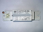
Preheat lamps use a combination filament/cathode at each end of the lamp in conjunction with a mechanical or automatic switch (see photo) that initially connect the filaments in series with the ballast and thereby preheat the filaments prior to striking the arc.
These systems are standard equipment in 240 V countries (and for 120 V lamps up to about 30 watts), and generally use a glow starter. Before the 1960s, four-pin thermal starters and manual switches were also used. Electronic starters are also sometimes used with these electromagnetic ballast lamp fittings.
The automatic glow starter shown in the photograph consists of a small gas-discharge tube, containing neon and/or argon and fitted with a bi-metallic electrode. The special bi-metallic electrode is the key to the automatic starting mechanism.
When starting the lamp, a glow discharge will appear over the electrodes of the starter. This glow discharge will heat the gas in the starter and cause the bi-metallic electrode to bend towards the other electrode. When the electrodes touch, the two filaments of the fluorescent lamp and the ballast will effectively be switched in series to the supply voltage. This causes the filaments to glow and emit electrons into the gas column by thermionic emission. In the starter's tube, the touching electrodes have stopped the glow discharge, causing the gas to cool down again. The bi-metallic electrode also cools down and starts to move back. When the electrodes separate, the inductive kick from the ballast provides the high voltage to start the lamp. The starter additionally has a capacitor wired in parallel to its gas-discharge tube, in order to prolong the electrode life.
Once the tube is struck, the impinging main discharge then keeps the cathode hot, permitting continued emission without the need for the starter to close. The starter does not close again because the voltage across the starter is reduced by the resistance in the cathodes and ballast. The glow discharge in the starter will not happen at the lower voltage so it will not warm and thus close the starter.
Tube strike is reliable in these systems, but glow starters will often cycle a few times before letting the tube stay lit, which causes undesirable flashing during starting. (The older thermal starters behaved better in this respect.)
If the tube fails to strike, or strikes but then extinguishes, the starting sequence is repeated. With automated starters such as glowstarters, a failing tube will cycle endlessly, flashing as the lamp quickly goes out because emission is insufficient to keep the lamp current high enough to keep the glowstarter open. This causes flickering, and runs the ballast at above design temperature. Some more advanced starters time out in this situation, and do not attempt repeated starts until power is reset. Some older systems used a thermal overcurrent trip to detect repeated starting attempts. These require manual reset.
[edit] Instant start
In some cases, a high voltage is applied directly: instant start fluorescent tubes simply use a high enough voltage to break down the gas and mercury column and thereby start arc conduction. These tubes can be identified by a single pin at each end of the tub. The lampholders have a "disconnect" socket at the low-voltage end to prevent electric shock. Low-cost lamps with integrated electronic ballast use this mode even if it reduces lamps lifespan.
[edit] Rapid start
Newer rapid start ballast designs provide filament power windings within the ballast; these rapidly and continuously warm the filaments/cathodes using low-voltage AC. No inductive voltage spike is produced for starting, so the lamps must be mounted near a grounded (earthed) reflector to allow the glow discharge to propagate through the tube and initiate the arc discharge. In some lamps a "starting aid" strip of grounded metal is attached to the outside of the lamp glass.
[edit] Electronic ballasts
Electronic ballasts typically work in rapid start or instant start mode.
Low cost ballasts mostly contain only a simple oscillator and series resonant LC circuit. When turned on, the oscillator starts, and the LC circuit charges. After a short time the voltage across the lamp reaches about 1kv and the lamp ignites. The process is too fast to preheat the cathodes, so the lamp instant-starts in cold cathode mode. The cathode filaments are still used for protection of the ballast from overheating if the lamp does not ignite. A few manufacturers use positive temperature coefficient (PTC) thermistors to disable instant starting and give some time to preheat the filaments.
More complex electronic ballasts use programmed start. The output AC frequency is started above the resonance frequency of the output circuit of the ballast; and after the filaments are heated, the frequency is rapidly decreased. If the frequency approaches the resonant frequency of the ballast, the output voltage will increase so much that the lamp will ignite. If the lamp does not ignite, an electronic circuit stops the operation of the ballast.
Since introduction in the 1990s, high frequency ballasts have been used with either rapid start or pre-heat lamps. These ballasts convert the incoming power to an output frequency in excess of 20 kHz. This increases lamp efficiency. These are used in several applications, including new generation tanning lamp systems, whereby a 100 watt lamp (e.g., F71T12BP) can be lit using 65 to 70 watts of actual power while obtaining the same lumens as magnetic ballasts. These ballasts operate with voltages that can be almost 600 volts, requiring some consideration in housing design, and can cause a minor limitation in the length of the wire leads from the ballast to the lamp ends.
[edit] End of life
The end of life failure mode for fluorescent lamps varies depending how they are used and their control gear type.
[edit] Emission mix

The "emission mix" on the tube filaments/cathodes is necessary to enable electrons to pass into the gas via thermionic emission at the tube operating voltages used. The mix is slowly sputtered off by bombardment with electrons and mercury ions during operation, but a larger amount is sputtered off each time the tube is started with cold cathodes. The method of starting the lamp has a significant impact on this. Lamps operated for typically less than 3 hours each switch-on will normally run out of the emission mix before other parts of the lamp fail. The sputtered emission mix forms the dark marks at the tube ends seen in old tubes. When all the emission mix is gone, the cathode cannot pass sufficient electrons into the gas fill to maintain the discharge at the designed tube operating voltage. Ideally, the control gear should shut down the tube when this happens. However, some control gear will provide sufficient increased voltage to continue operating the tube in cold cathode mode, which will cause overheating of the tube end and rapid disintegration of the electrodes and their support wires until they are completely gone or the glass cracks, wrecking the low pressure gas fill and stopping the gas discharge.
[edit] Ballast electronics
This may occur in compact fluorescent lamps with integral electrical ballasts or in linear lamps. Ballast electronics failure is a somewhat random process which follows the standard failure profile for any electronic devices. Integral electronic ballasts suffer from shortened lifespans in high humidity applications. There is an initial small peak of early failures, followed by a drop and steady increase over lamp life. Life of electronics is heavily dependent on operating temperature—it typically halves for each 10 °C temperature rise. The quoted average life of a lamp is usually at 25 °C ambient (this may vary by country). The average life of the electronics at this temperature is normally greater than this, so at this temperature, not many lamps will fail due to failure of the electronics. In some fittings, the ambient temperature could be well above this, in which case failure of the electronics may become the predominant failure mechanism. Similarly, running a compact fluorescent lamp base-up will result in hotter electronics and shorter average life (particularly with higher power rated ones). Electronic ballasts should be designed to shut down the tube when the emission mix runs out as described above. In the case of integral electronic ballasts, since they never have to work again, this is sometimes done by having them deliberately burn out some component to permanently cease operation.
[edit] Phosphor
The phosphor drops off in efficiency during use. By around 25,000 operating hours, it will typically be half the brightness of a new lamp (although some manufacturers claim much longer half-lives for their lamps). Lamps which do not suffer failures of the emission mix or integral ballast electronics will eventually develop this failure mode. They still work, but have become dim and inefficient. The process is slow, and often only becomes obvious when a new lamp is operating next to an old lamp.
[edit] Loss of mercury
Mercury is slowly absorbed into glass, phosphor, and tube electrodes throughout the lamp life, where it can no longer function. Newer lamps now have just enough mercury to last the expected life of the lamp. Loss of mercury will take over from failure of the phosphor in some lamps. The failure symptoms are similar, except loss of mercury initially causes an extended run-up time to full light output, and finally causes the lamp to glow a dim pink when the mercury runs out and the argon base gas takes over as the primary discharge.
[edit] Phosphors and the spectrum of emitted light
The spectrum of light emitted from a fluorescent lamp is the combination of light directly emitted by the mercury vapor, and light emitted by the phosphorescent coating. The spectral lines from the mercury emission and the phosphorescence effect give a combined spectral distribution of light that is not similar to those produced by incandescent sources. The relative intensity of light emitted in each narrow band of wavelengths over the visible spectrum is in different proportions compared to that of an incandescent source. Colored objects are perceived differently under light sources with differing spectral distributions. For example, some people find the color rendition produced by some fluorescent lamps to be harsh and displeasing. A healthy person can sometimes appear to have an unhealthy skin tone under fluorescent lighting. The extent to which this phenomenon occurs is related to the light's spectral composition, and may be gauged by its Color Rendering Index (CRI).
[edit] Color rendering index
CRI is a measure of how well balanced the different color components of the white light are, relative to daylight or a blackbody. By definition, an incandescent lamp has a CRI of 100. Real-life fluorescent tubes achieve CRIs of anywhere from 50% to 99%. Fluorescent lamps with low CRI have phosphors which emit too little red light. Skin appears less pink, and hence "unhealthy" compared with incandescent lighting. Colored objects appear muted. For example, a low CRI 6800K halophosphate tube (an extreme example) will make reds appear dull red or even brown. Since the eye is relatively less efficient at detecting red light, an improvement in color rendering index, with increased energy in the red part of the spectrum, may reduce the overall luminous efficacy. [2]
[edit] Color temperature
Correlated color temperature (CCT) is a measure of the "shade" of whiteness of a light source, again by comparison with a blackbody. Typical incandescent lighting is 2700K which is yellowish-white. Halogen lighting is 3000K. Fluorescent lamps are manufactured to a chosen CCT by altering the mixture of phosphors inside the tube. Warm-white fluorescents have CCT of 2700K and are popular for residential lighting. Neutral-white fluorescents have a CCT of 3000K or 3500K. Cool-white fluorescents have a CCT of 4100K and are popular for office lighting. Daylight fluorescents have a CCT of 5000K to 6500K, which is bluish-white.
High CCT lighting generally requires higher light levels. At dimmer illumination levels, the human eye perceives lower color temperatures as more natural, as related through the Kruithof curve. So, a dim 2700K incandescent lamp appears natural and a bright 5000K lamp also appears natural, but a dim 5000K fluorescent lamp appears too pale. Daylight-type fluorescents look natural only if they are very bright.
[edit] Phosphor composition
Some of the least pleasant light comes from tubes containing the older halophosphate type phosphors (chemical formula Ca5(PO4)3(F,Cl):Sb3+,Mn2+). The bad color reproduction is due to the fact that this phosphor mainly emits yellow and blue light, and relatively little green and red. In the absence a reference, this mixture appears white to the eye, but the light has an incomplete spectrum. The CRI of such lamps is around 60.
Since the 1990s, higher quality fluorescent lamps use either a higher CRI halophosphate coating, or a triphosphor mixture, based on europium and terbium ions, that have emission bands more evenly distributed over the spectrum of visible light. High CRI halophosphate and triphosphor tubes give a more natural color reproduction to the human eye. The CRI of such lamps is typically 82-100.
| Fluorescent lamp spectra | |||
|---|---|---|---|
| Typical fluorescent lamp with "rare earth" phosphor |  |
A typical "cool white" fluorescent lamp utilizing two rare earth doped phosphors, Tb3+, Ce3+:LaPO4 for green and blue emission and Eu:Y2O3 for red. For an explanation of the origin of the individual peaks click on the image. Note that several of the spectral peaks are directly generated from the mercury arc. This is likely the most common type of fluorescent lamp in use today. | |
| An older style halophosphate phosphor fluorescent lamp |  |
Halophosphate phosphors in these lamps usually consist of trivalent antimony and divalent manganese doped calcium halophosphate (Ca5(PO4)3(Cl,F):Sb3+, Mn2+). The color of the light output can be adjusted by altering the ratio of the blue emitting antimony dopant and orange emitting manganese dopant. The color rendering ability of these older style lamps is quite poor. Halophosphate phosphors were invented by A.H. McKeag et al. in 1942. | |
| "Natural sunshine" fluorescent light |  |
An explanation of the origin of the peaks is on the image page. | |
| Yellow fluorescent lights |  |
The spectrum is nearly identical to a normal fluorescent bulb except for a near total lack of light below 500 nanometers. This effect can be achieved through either specialized phosphor use or more commonly by the use of a simple yellow light filter. These lamps are commonly used as lighting for photolithography work in cleanrooms and as "bug repellent" outdoor lighting (the efficacy of which is questionable). | |
| Spectrum of a "blacklight" bulb |  |
There is typically only one phosphor present in a blacklight bulb, usually consisting of europium-doped strontium fluoroborate which is contained in an envelope of Wood's glass. | |
[edit] Usage
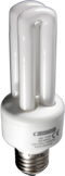
Fluorescent light bulbs come in many shapes and sizes. The compact fluorescent light bulb (CF) is becoming more popular. Many compact fluorescent lamps integrate the auxiliary electronics into the base of the lamp, allowing them to fit into a regular light bulb socket.
In the US, residential use of fluorescent lighting remains low (generally limited to kitchens, basements, hallways and other areas), but schools and businesses find the cost savings of fluorescents to be significant and rarely use incandescent lights.
Lighting arrangements use fluorescent tubes in an assortment of tints of white. Sometimes this is because of the lack of appreciation for the difference or importance of differing tube types. Mixing tube types within fittings improves the color reproduction of lower quality tubes. Tax incentives and environmental awareness result in higher use in places such as California.
In other countries, residential use of fluorescent lighting varies depending on the price of energy, financial and environmental concerns of the local population, and acceptability of the light output. In East and Southeast Asia it is very rare to see incandescent bulbs in buildings anywhere.
In February 2007, Australia enacted a law that will ban most sales of incandescent light bulbs by 2010.[3] While the law does not specify which alternative Australians are to use, compact fluorescents are likely to be the primary replacements. In April 2007, Canada announced a similar plan to phase out the sale of incandescent bulbs by 2012. Finnish parliament has been discussing banning sales of incandescent light bulbs by the beginning of 2011.[4] The UK government announced in 2007 that incandescent bulbs would be phased out by 2011.[5]
[edit] Advantages
[edit] Luminous efficacy
Fluorescent lamps convert more of the input power to visible light than incandescent lamps. A typical 100 watt tungsten filament incandescent lamp may convert only 10% of its power input to visible white light, whereas typical fluorescent lamps convert about 22% of the power input to visible white light.[6] See the table in the luminous efficacy article.
The efficacy of fluorescent tubes ranges from about 16 lumens per watt for a 4 watt tube with an ordinary ballast to as high as about 100 lumens per watt for a 32 watt tube with modern electronic ballast, commonly averaging 50 to 67 lm/W overall. Most compact fluorescents above 13 watts with integral electronic ballasts achieve about 60 lm/W. Lamps are rated by lumens after 100 hours of operation.[7] For a given fluorescent tube, a high-frequency electronic ballast gives about 10% efficacy improvement over an inductive ballast. It is necessary to include the ballast loss when evaluating the efficacy of a fluorescent lamp system; this can be about 25% of the lamp power with magnetic ballasts, and around 10% with electronic ballasts.
Fluorescent lamp efficacy is dependent on lamp temperature at the coldest part of the lamp. In T8 lamps this is in the center of the tube. In T5 lamps this is at the end of the tube with the text stamped on it. The ideal temperature for a T8 lamp is 25 °C (77 °F) while the T5 lamp is ideally at 35 °C (95 °F).
[edit] Life
Typically a fluorescent lamp will last between 10 to 20 times as long as an equivalent incandescent lamp when operated several hours at a time.
The higher initial cost of a fluorescent lamp is usually more than compensated for by lower energy consumption over its life. The longer life may also reduce lamp replacement costs, providing additional saving especially where labour is costly. Therefore they are widely used by businesses and institutions, but not as much by households.
[edit] Lower luminosity
Compared with an incandescent lamp, a fluorescent tube is a more diffuse and physically larger light source. In suitably designed lamps, light can be more evenly distributed without point source of glare such as seen from an undiffused incandescent filament.
[edit] Lower heat
About two-thirds to three-quarters less heat is given off by fluorescent lamps compared to an equivalent installation of incandescent lamps. This greatly reduces the size, cost, and energy consumption of air-conditioning equipment.

[edit] Disadvantages
[edit] Frequent switching
If the lamp is installed where it is frequently switched on and off, it will age rapidly. Under extreme conditions, its lifespan may be much shorter than a cheap incandescent lamp. Each start cycle slightly erodes the electron-emitting surface of the cathodes; when all the emission material is gone, the lamp cannot start with the available ballast voltage. Fixtures intended for flashing of lights (such as for advertising) will use a ballast that maintains cathode temperature when the arc is off, preserving the life of the lamp.
[edit] Health and safety issues
If a fluorescent lamp is broken, mercury can contaminate the surrounding environment. A 1987 report described a 23-month-old toddler hospitalized due to mercury poisoning traced to a carton of 8-foot fluorescent lamps that had broken. The glass was cleaned up and discarded, but the child often used the area for play.[8]
Fluorescent lamps emit a small amount of UV light, and a recent study in the US found that UV exposure from sitting under fluorescent lights for eight hours is equivalent to only one minute of sun exposure.[9] However, UV light can affect sensitive paintings, especially watercolors and many textiles, so valuable art work must be protected from fluorescent lighting. The UV light causes UV degradation and can also cause pigment fading.[citation needed]
Since fluorescent lamps produce a small amount of UV light, they can trigger problems among individuals with very high pathological sensitivity to ultraviolet light. They can induce disease activity in very photosensitive individuals with Systemic lupus erythematosus; standard acrylic diffusers absorb UV-B radiation and appear to protect against this.[10] In rare cases individuals with solar urticaria (allergy to sunlight) can get a rash from fluorescent lighting.[11] Fluorescent lamps with magnetic ballasts flicker at a normally unnoticeable frequency of 100 or 120 Hertz and this flickering can cause problems for individuals with light sensitivity,[12] they are listed as problematic for individuals with epilepsy,[13] lupus,[14] chronic fatigue syndrome, and vertigo.[15] Research on this is very limited. Fluorescent lighting can also induce depersonalization and derealization, subsequently, it can worsen depersonalization disorder symptomology.[16]
[edit] Ballast

Fluorescent lamps require a ballast to stabilize the current through the lamp, and to provide the initial striking voltage required to start the arc discharge. This increases the cost of fluorescent light fixtures, though often one ballast is shared between two or more lamps. Electromagnetic ballasts with a minor fault can produce an audible humming or buzzing noise. Magnetic ballasts are usually filled with a tar-like potting compound to reduce emitted noise. Hum is eliminated in lamps with a high-frequency electronic ballast. Energy lost in magnetic ballasts can be significant, on the order of 10% of lamp input power.[17] Electronic ballasts reduce this loss.
[edit] Power quality and radio interference
Simple inductive fluorescent lamp ballasts have a power factor of less than unity. Inductive ballasts include power factor correction capacitors. Simple electronic ballasts may also have low power factor due to their rectifier input stage.
Fluorescent lamps are a non-linear load and generate harmonic currents in the electrical power supply. The arc within the lamp may generate radio frequency noise, which can be conducted through power wiring. Suppression of radio interference is possible. Very good suppression is possible, but adds to the cost of the fluorescent fixtures.
[edit] Operating temperature
Fluorescent lamps operate best around room temperature. At much lower or higher temperatures, efficiency decreases. At below-freezing temperatures standard lamps may not start. Special lamps may be needed for reliable service outdoors in cold weather.
[edit] Lamp shape
Fluorescent tubes are long, low-luminance sources compared with high pressure arc lamps and incandescent lamps. However, low luminous intensity of the emitting surface is useful because it reduces glare. Lamp fixture design must control light from a long tube instead of a compact globe.
The compact fluorescent lamp (CFL) replaces regular incandescent bulbs. However, some CFLs will not fit some lamps, because the harp (heavy wire shade support bracket) is shaped for the narrow neck of an incandescent lamp. CFLs tend to have a wide housing for their electronic ballast close to the bulb's base, and so may not fit some lamps.
[edit] Flicker problems
Fluorescent lamps using a magnetic mains frequency ballast do not give out a steady light; instead, they flicker at twice the supply frequency. While this is not easily discernible by the human eye, it can cause a strobe effect, where something spinning at just the right speed may appear stationary if illuminated solely by a single fluorescent lamp. This effect is eliminated by paired lamps operating on a lead-lag ballast. Unlike a true strobe lamp, the light level drops in appreciable time and so substantial "blurring" of the moving part would be evident.
In some circumstances, fluorescent lamps operated at mains frequency can also produce flicker at the mains frequency (50 or 60 Hz) itself, which is noticeable by more people. This can happen in the last few hours of tube life when the cathode emission coating at one end is almost run out, and that cathode starts having difficulty emitting enough electrons into the gas fill, resulting in slight rectification and hence uneven light output in positive and negative going mains cycles. Mains frequency flicker can also sometimes be emitted from the very ends of the tubes, if each tube electrode produces slightly different light output pattern on each half-cycle. Flicker at mains frequency is more noticeable in the peripheral vision than it is in the center of gaze.
New fluorescent lamps may show a twisting spiral pattern of light in a part of the lamp. This effect is due to loose cathode material and usually disappears after a few hours of operation.[18]
Electromagnetic ballasts may also cause problems for video recording as there can be a 'beat effect' between the periodic reading of a camera's sensor and the fluctuations in intensity of the fluorescent lamp. When other devices that also flicker, such as CRT-based computer monitors, are operated under fluorescent lighting, the flicker may become much more noticeable.
Full-size and compact fluorescent lamps using high-frequency electronic ballasts do not produce visible light flicker, since the phosphor persistence is longer than a half cycle of the higher operation frequency. Operating frequencies of electronic ballasts are selected to avoid interference with infrared remote controls.
The non-visible 100 Hz - 120 Hz flicker from fluorescent tubes powered by electromagnetic ballasts are associated with headaches and eyestrain. Individuals with high flicker fusion threshold are particularly affected by electromagnetic ballasts: their EEG alpha waves are markedly attenuated and they perform office tasks with greater speed and decreased accuracy. [19] Ordinary people have better reading performance using high frequency (20 kHz – 60 kHz) electronic ballasts than electromagnetic ballasts.[20]
The flicker of fluorescent lamps, even with electromagnetic ballasts, is so rapid that it is unlikely to present a hazard to individuals with epilepsy.[21] Early studies suspected a relationship between the flickering of fluorescent lamps with electromagnetic ballasts and repetitive movement in autistic children.[22] However, these studies had interpretive problems[23] and have not been replicated.
[edit] Dimming
Fluorescent light fixtures cannot be connected to the same dimmer switch used for incandescent lamps. Two effects are responsible for this: the waveshape of the voltage emitted by a standard phase-control dimmer interacts badly with many ballasts, and it becomes difficult to sustain an arc in the fluorescent tube at low power levels. Dimming installations require 4-pin fluorescent lamps and compatible dimming ballasts. These systems keep the cathodes of the fluorescent tube fully heated even as the arc current is reduced, promoting easy thermionic emission of electrons into the arc stream. CFLs are available that work in a dimmer circuit.
[edit] Disposal and recycling
The disposal of phosphor and particularly the toxic mercury in the tubes is an environmental issue. Governmental regulations in many areas require special disposal of fluorescent lamps separate from general and household wastes. For large commercial or industrial users of fluorescent lights, recycling services are available in many nations, and may be required by regulation. In some areas, recycling is also available to consumers. The need for a recycling infrastructure is an issue with instituting proposed bans of incandescent bulbs.
The amount of mercury in a fluorescent lamp varies from 3 to 46 mg, depending on lamp size and age.[24] Newer lamps contain less mercury and the 3–4 mg versions are sold as low-mercury types. A typical 2006-era 4 ft (122 cm) T-12 fluorescent lamp (i.e., F32T12) contains about 12 milligrams of mercury.[25] In early 2007, the National Electrical Manufacturers Association in the US announced that "Under the voluntary commitment, effective April 15, 2007, participating manufacturers will cap the total mercury content in CFLs under 25 watts at 5 milligrams (mg) per unit. CFLs that use 25 to 40 watts of electricity will have total mercury content capped at 6 mg per unit."[26]
A broken fluorescent tube will release its mercury content. Safe cleanup of broken fluorescent bulbs differs from cleanup of conventional broken glass or incandescent bulbs. 99% of the mercury is typically contained in the phosphor, especially on lamps that are near their end of life.[27]
At least some of the early (around 1940) fluorescent lamps used toxic beryllium compounds. [28]. However, it is very unlikely that one would encounter any such lamps.[29]
[edit] Tube designations
Lamps are typically identified by a code such as F##T##, where F is for fluorescent, the first number indicates the power in watts (or where lamps can be operated at different power levels, the length in inches), the T indicates that the shape of the bulb is tubular, and the last number is the diameter in eighths of an inch (sometimes in millimeters, rounded to the nearest millimeter). Typical diameters are T12 or T38 (11/2" Ø or 38.1 mm Ø) for residential bulbs with old magnetic ballasts, T8 or T26 (1" Ø or 25.4 mm Ø) for commercial energy-saving lamps with electronic ballasts, and T5 or T16 (5/8" Ø or 15.875 mm Ø) for very small lamps which may even operate from a battery powered device.
| Fluorescent tube diameter designation comparison | ||||||
|---|---|---|---|---|---|---|
| Tube diameter designations | Tube diameter measurements | Extra | ||||
| Imperial-based | Metric-based | Inches | Millimeters | Socket | Notes | |
| T4 | N/A | 4/8 | 12 | G5 bipin | Slim lamps, tube lengths may vary | |
| T5 | T16 | 5/8 | 15.875 | G5 bipin | Supersedes T8, introduced in the 1990s[30] | |
| T8 | T26 | 8/8 | 1" | 25.4 | G13 bipin/Single Pin/Recessed Double contact | From the 1930s[31]. More common since the 1980s[32] |
| T9 | T29 | 9/8 | 11/8 | 28.575 | Circular fluorescent tubes only | |
| T12 | T38 | 12/8 | 11/2 | 38.1 | G13 bipin/single pin, Recessed Double contact | Also from the 1930s. Not as efficient as new lamps[33] |
| PG17 | N/A | 17/8 | 21/8 | 53.975 | Recessed Double Contact | General Electric's Power Groove tubes only |
[edit] Reflectors

Some lamps have an internal opaque reflector. Coverage of the reflector ranges from 120 degrees to 310 degrees of the lamp's circumference. Lamps that have significantly more than 210 degrees of coverage are often referred to as "aperture lamps" as the amount of open area that light can escape is significantly less than the area that acts as an internal reflector. Often, a lamp is marked as a reflector lamp by adding the letter "R" in the model code, so a F##T## lamp with a reflector would be coded as "FR##T##". VHO lamps with reflectors may be coded as VHOR. No such designation exists for the amount of reflector degrees the lamp has.
Reflector lamps are used in when light is only desired to be emitted in a single direction, or when an application requires the maximum amount of light. For example, these lamps can be used in tanning beds or in backlighting electronic displays. An internal reflector is more efficient than standard external reflectors as there is less opportunity to lose light due to wave cancellation. Another example is color matched aperture lights (30 degrees of opening, give or take) are used in the food industry for quality control purposes, to allow robotic inspection of cooked goods.
[edit] Slimline lamps
Slimline lamps operate on an instant start ballast and are recognizable by their single-pin bases.
[edit] High Output/Very High Output Lamps
High-output lamps are brighter and draw more electrical current, have different ends on the pins so they cannot be used in the wrong fixture, and are labeled F##T##HO, or F##T##VHO for very high output. Since about the early to mid 1950s to today, General Electric developed and improved the Power Groove lamp with the label F##PG17. These lamps are recognizable by their large diameter (17/8" or 21/8"), grooved tube shape and an R17d cap on each end of them.
[edit] Other tube shapes
U-shaped tubes are FB##T##, with the B meaning "bent". Most commonly, these have the same designations as linear tubes. Circular bulbs are FC##T#, with the diameter of the circle (not circumference or watts) being the first number, and the second number usually being 9 (29 mm) for standard fixtures.
[edit] Colors
Color is usually indicated by WW for warm white, EW for enhanced (neutral) white, CW for cool white (the most common), and DW for the bluish daylight white. BLB is used for blacklight-blue lamps commonly used in bug zappers. BL is used for blacklight lamps commonly used in nightclubs. Other non-standard designations apply for plant lights or grow lights.
Philips and Osram use numeric color codes for the colors. On Tri-Phosphor and Multi-Phosphor tubes, the first digit indicates the Color Rendition Index of the lamp. If the first digit on a lamp says 8, then the CRI of that lamp will be approximately 85. The last two digits indicate the Color Temperature of the lamp in Kelvins (K). For example, if the last two digits on a lamp say 40, that lamp's Color Temperature will be 4000 K, which is a common Tri-Phosphor Cool White fluorescent lamp.
| Halophosphate tubes | |||
|---|---|---|---|
| Numeric color code | Color | Approximate CRI | Color temperature (K) |
| 27 | Warm white | 50 - 79 | 2700 |
| 33 | Cool white | 50 - 79 | 4000 |
| 83 | Medium warm white | 80 | 3000 |
| 84 | Cool white (high CRI) | 80 | 4000 |
| Tri-phosphor tubes | |||
| Numeric color code | Color | Approximate CRI | Color temperature (K) |
| 827 | Warm white | ~85 | 2700 |
| 840 | Cool white | ~85 | 4000 |
| 865 | Cool daylight | ~85 | 6500 |
| Multi-phosphor tubes | |||
| Numeric color code | Color | Approximate CRI | Color temperature (K) |
| 927 | Warm white | ~95 | 2700 |
| 940 | Cool white | ~95 | 4000 |
| 965 | Cool daylight | ~95 | 6500 |
| Special purpose tubes | |||
| Numeric code | Fluorescent
lamp type |
Notes | |
| 05 | Germicidal lamps | No phosphors used at all,
using an envelope of fused quartz. |
|
| 08 | Black-light lamps | ||
| 09 | Sun-tanning lamps | ||
[edit] Lengths
Unusual lengths are typically added after the color. One example is an F25T12/CW/33, meaning 25 Watts, 11/2" diameter, Cool White, 33" or 84 cm long. Without the 33", it would be assumed that an F25T12 is the more-common 30" long.
[edit] Compact fluorescent lamps
Some compact fluorescents are now being labelled with this designation system.
[edit] Other fluorescent lamps
- Black lights
- Blacklights are a subset of fluorescent lamps that are used to provide short-wave ultraviolet light (at about 360nm wavelength). They are built in the same fashion as conventional fluorescent lamps but the glass tube is coated with a phosphor that converts the short-wave UV within the tube to long-wave UV rather than to visible light. They are used to provoke fluorescence (to provide dramatic effects using blacklight paint and to detect materials such as urine and certain dyes that would be invisible in visible light) as well as to attract insects to bug zappers.
- So-called blacklite blue lamps are also made from more expensive deep purple glass known as Wood's glass rather than clear glass. The deep purple glass filters out most of the visible colors of light directly emitted by the mercury-vapor discharge, producing proportionally less visible light compared with UV light. This allows UV-induced fluorescence to be seen more easily (thereby allowing blacklight posters to seem much more dramatic). The blacklight lamps used in bug zappers do not require this refinement so it is usually omitted in the interest of cost; they are called simply blacklite (and not blacklite blue).
- Tanning lamps
- The lamps used in tanning beds contain a different phosphor blend (typically 3 to 5 or more phosphors) that emits both UVA and UVB, provoking a tanning response in most human skin. Typically, the output is rated as 3% to 10% UVB (5% most typical) with the remaining UV as UVA. These are mainly F71, F72 or F73 HO (100W) lamps, although 160W VHO are somewhat common.
- Grow lamps
- Grow lamps contain phosphor blends that encourage photosynthesis, growth, and/or flowering in plants, algae, photosynthetic bacteria, and other light-dependent organisms.
- Germicidal lamps
- Germicidal lamps contain no phosphor at all (technically making them gas discharge lamps rather than fluorescent) and their tubes are made of fused quartz that is transparent to the short-wave UV directly emitted by the mercury discharge. The UV emitted by these tubes will kill germs, ionize oxygen to ozone, and cause eye and skin damage. Besides their uses to kill germs and create ozone, they are sometimes used by geologists to identify certain species of minerals by the color of their fluorescence. When used in this fashion, they are fitted with filters in the same way as blacklight-blue lamps are; the filter passes the short-wave UV and blocks the visible light produced by the mercury discharge. They are also used in EPROM erasers.
- Germicidal lamps have designations beginning with G (meaning 'Germicidal'), rather than F, for example G30T8 for a 30-Watt, 1 inch diameter, 36 inch long germicidal lamp (as opposed to an F30T8, which would be the fluorescent lamp of the same size and rating).
- Electrodeless lamps
- Electrodeless induction lamps are fluorescent lamps without internal electrodes. They have been commercially available since 1990. A current is induced into the gas column using electromagnetic induction. Because the electrodes are usually the life-limiting element of fluorescent lamps, such electrodeless lamps can have a very long service life, although they also have a higher purchase price.
- Compact fluorescent lamps (CFL)
- Also known as a compact fluorescent light bulb is a type of fluorescent lamp designed to replace an incandescent lamp. Many CFLs can fit in existing incandescent light fixtures.
- Cold-cathode fluorescent lamps (CCFL)
- Cold-cathode fluorescent lamps are used as backlighting for LCD displays in personal computer and TV monitors. They are also popular with case modders in recent years.
[edit] Science demonstrations
Fluorescent lamps can be illuminated by means other than a proper electrical connection. These other methods however result in very dim or very short-lived illumination, and so are seen mostly in science demonstrations. With the exception of static electricity (and Van de Graaff generators), these methods can be very dangerous if done improperly:
- Static electricity
- Van de Graaff generator
- Tesla coil
- Capacitive coupling with high-voltage power lines[34]
[edit] Film and video use
Special fluorescent lights are often used in film and video production. The brand name Kino Flo are used to create softer fill light and are less hot than traditional halogen light sources. These fluorescent lights are designed with special high-frequency ballasts to prevent video flickering and high color-rendition index bulbs to approximate daylight color temperatures.
[edit] See also
[edit] References
- ^ U.S. Patent 865367 Fluorescent Electric Lamp
- ^ General Electric, Fluorescent Lamps TP 111 R page 8
- ^ "Australia Bans Traditional Light Bulbs to Combat Global Warming". green wombat blog. 2007-02-20. http://blogs.business2.com/greenwombat/2007/02/australia_bans_.html. Retrieved on 2007-12-31.
- ^ "Ban on incandescent lamps discussed by Finnish Parliament". Helsingin Sanomat - International Edition. 2007-09-27. http://www.hs.fi/english/article/Ban+on+incandescent+lamps+discussed+by+Finnish+Parliament/1135230613491. Retrieved on 2007-12-31.
- ^ "Switch off for traditional bulbs". BBC. 2007-09-27. http://news.bbc.co.uk/1/hi/uk/7016020.stm. Retrieved on 2009-01-17.
- ^ General Electric Fluorescent Lamps TP111R, page 20
- ^ Klipstein, Donald L.. "Light and Lighting Facts and Bits of Data!". http://members.misty.com/don/. Retrieved on 2007-12-29.
- ^ Tunnessen WW Jr, McMahon KJ, Baser M (1987). "Acrodynia: exposure to mercury from fluorescent light bulbs". Pediatrics 79 (5): 786–9. PMID 3575038.
- ^ Lytle et al., "An Estimation of Squamous Cell Carcinoma Risk from Ultraviolet Radiation Emitted by Fluorescent Lamps"; Photodermatol Photoimmunol Photomed (1993)
- ^ Rihner M, McGrath H Jr (1992). "Fluorescent light photosensitivity in patients with systemic lupus erythematosus". Arthritis Rheum 35 (8): 949–52. doi:. PMID 1642660.
- ^ Beattie PE, Dawe RS, Ibbotson SH, Ferguson J (2003). "Characteristics and prognosis of idiopathic solar urticaria: a cohort of 87 cases". Arch Dermatol 139 (9): 1149–54. doi:. PMID 12975156. http://archderm.ama-assn.org/cgi/content/full/139/9/1149.
- ^ Working with Light Sensitivity
- ^ Accommodation Ideas for Employees with Epilepsy
- ^ Accommodation and Compliance Series: Employees with Lupus
- ^ Accommodating People with Vertigo
- ^ Simeon D, Knutelska M, Nelson D & Guralnik O. (2003) Feeling unreal: a depersonalization disorder update of 117 cases. Journal of Clinical Psychiatry 64 (9): 990-7 PMID 14628973
- ^ GE TP 111 R
- ^ General Electric Fluorescent Lamps TP 111R, Dec. 1978, page 22
- ^ Küller R, Laike T (1998). "The impact of flicker from fluorescent lighting on well-being, performance and physiological arousal". Ergonomics 41 (4): 433–47. doi:.
- ^ Veitch JA, McColl SL (1995). "Modulation of fluorescent light: flicker rate and light source effects on visual performance and visual comfort". Light Res Tech 27 (4): 243–256. http://irc.nrc-cnrc.gc.ca/pubs/fulltext/nrcc38944/. Retrieved on 2007-08-12.
- ^ Binnie CD, de Korte RA, Wisman T (1979). "Fluorescent lighting and epilepsy". Epilepsia 20 (6): 725–7. doi:. PMID 499117.
- ^ Colman RS, Frankel F, Ritvo E, Freeman BJ (1976). "The effects of fluorescent and incandescent illumination upon repetitive behaviors in autistic children". J Autism Child Schizophr 6 (2): 157–62. doi:. PMID 989489.
- ^ Turner M (1999). "Annotation: Repetitive behaviour in autism: a review of psychological research". J Child Psychol Psychiatry 40 (6): 839–49. doi:. PMID 10509879.
- ^ Page 183 of http://www.chem.unep.ch/MERCURY/Toolkit/UNEP-final-pilot-draft-toolkit-Dec05.pdf
- ^ Lighting Design Lab Articles - Mercury in Fluorescent Lamps
- ^ NEMA Voluntary Commitment on Mercury in CFLs
- ^ Floyd, et al. (2002), quoted on page 184 of Toolkit for identification and quantification of mercury releases (PDF)
- ^ http://www.nyu.edu/classes/jaeger/beryllium.htm Beryllium toxicity and fluorescent lamp manufacture, retrieved June 7,2008
- ^ General Electric Fluorescent Lamps TP 111R, Dec. 1978, says on pg. 23 that since 1949 GE lamps used relatively inert phosphates found to be safe in ordinary handling of either the intact or broken lamp.
- ^ "EC&M: The T5 Fluorescent Lamp: Coming on Strong". 2003-09-01. http://ecmweb.com/ops/electric_fluorescent_lamp_coming/. Retrieved on 2008-09-28.
- ^ "Covington, E. J. The Story Behind This Account of Fluorescent Lamp Development". http://home.frognet.net/~ejcov/thayer.html. Retrieved on 2008-09-28.
- ^ "Lawrence Berkeley National Laboratory: T-8 lamp retrofits". http://ateam.lbl.gov/Design-Guide/DGHtm/t.8lampretrofits.htm. Retrieved on 2008-09-28.
- ^ "Lawrence Berkeley National Laboratory: History and problems of T12 fluorescent lamps". http://ateam.lbl.gov/Design-Guide/DGHtm/historyandproblemsoft12fluorescentlamps.htm. Retrieved on 2008-09-28.
- ^ Richardbox.com at Internet Archive.
[edit] External links
| Wikimedia Commons has media related to: Fluorescent lamp |
| Look up Fluorescent lamp in Wiktionary, the free dictionary. |
- T5 Fluorescent Systems - Lighting Research Center Research about the improved T5 relative to the previous T8 standard
- NASA: The Fluorescent Lamp: A plasma you can use
- Video How Fluorescent Tubes are Manufactured
- Museum of Electric Lamp Technology
- R. N. Thayer (1991-10-25). "The Fluorescent Lamp: Early U. S. Development". The Report courtesy of General Electric Company. http://home.frognet.net/~ejcov/thayer.html. Retrieved on 2007-03-18.
|
|||||||||||||||||||||||||