S-Video
From Wikipedia, the free encyclopedia
| S-Video | ||
|---|---|---|
|
|
||
| Type | Analog video connector | |
| Specifications | ||
| Hot pluggable | yes | |
| External | yes | |
| Video signal | NTSC, PAL or SECAM video | |
| Pins | 4 or 7 | |
| Connector | Mini-DIN connector | |
| Pin out | ||
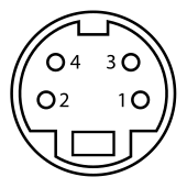 Female Connector |
||
| Pin 1 | GND | Ground (Y) |
| Pin 2 | GND | Ground (C) |
| Pin 3 | Y | Intensity (Luminance) |
| Pin 4 | C | Color (Chrominance) |

Separate Video, more commonly known as S-Video, and sometimes incorrectly referred to as "Super Video"[1] and also known as Y/C, is an analog video signal that carries the video data as two separate signals, lumen (luminance) and chroma (colour). This differs from composite video which carries picture information as a single lower-quality signal, and component video which carries picture information as three separate higher-quality signals. S-Video carries standard definition video (typically at 480i or 576i resolution), but does not carry audio on the same cable.
The 4-pin mini-DIN connector (shown at right) is the most common of several S-Video connector types. Other S-Video connector variants include 7-pin locking "dub" connectors used on many professional S-VHS machines, and dual "Y" and "C" BNC connectors, often used for S-Video patch bays. Early Y/C video monitors often used RCA connectors that were switchable between Y/C and composite video input. Though the connectors are different, the Y/C signals for all types are compatible.
Contents |
[edit] Overview
|
|
This section (specifically the colour resolution part, which is bogus) may require cleanup to meet Wikipedia's quality standards. Please improve this section (specifically the colour resolution part, which is bogus) if you can. (March 2009) |

The luminance (Y; gray-scale) signal and modulated chrominance (C; colour) information are carried on separate synchronised signal and ground pairs.
In composite video, the luminance signal is low-pass filtered to prevent crosstalk between high-frequency luminance information and the colour sub-carrier. S-Video maintains the two as separate signals, so that detrimental low-pass filtering is unnecessary. This increases bandwidth for the luminance information, and also subdues the colour crosstalk problem. The infamous dot crawl is eliminated. This means that S-Video leaves more information from the original video intact; thus, it offers an improved image reproduction compared to composite video.
Due to the separation of the video into brightness and colour components, S-Video is sometimes considered a type of component video signal; however, it is also the poorest quality-wise, being far surpassed by the more complex component video schemes (like RGB). What differentiates S-Video from these higher component video schemes is that S-Video carries the colour information as one signal. This means that the colour has to be encoded in some way, and as such, NTSC, PAL and SECAM signals are all decidedly different through S-Video. Thus, for full compatibility, the connected devices not only have to be S-Video compatible but also compatible in terms of colour encoding. In addition, S-Video suffers from reduced colour resolution. NTSC S-Video colour resolution is typically 120 lines horizontal (approximately 160 pixels edge-to-edge), versus 250 lines horizontal for a DVD-encoded signal, or 30 lines horizontal for standard VCRs.
When used for connecting a video source to a video display where both support 4:3 and 16:9 display formats, the PAL television standard provides for signaling pulses that will automatically switch the display from one format to the other. The S-video connection transparently supports this operation. The S-Video connection also has general provision for widescreen signaling through a DC offset applied to the chrominance signal; however, this is a more recent development, and is not widely supported.
[edit] History
In the video equipment market since the early 1980s, JVC's 1987 release of the S-VHS image introduced the S-Video cable standard to the home video equipment market. JVC claimed that only with S-video cables could the new image standard play with its full visual potential, despite the s-video cable not included with early S-VHS-capable VCRs, because of low market penetration of television sets equipped with S-Video input ports. Commercially, the S-VHS format never became a mainstream image standard, yet it was the videographic standard in Home Theater video.
In the late 1990s, big-screen television sets featured the S-video port as the default video input, thus increasing the number of supportable electronic devices (videocassette recorder, DVD player, satellite receiver, video game console, and computer Video card). The introduction of Component video, commercially replaced S-video in the home video market, yet is the default input port of modern video device, as alternative to the composite video image standard, and for video signal output from a computer to a television set.
Etymologically, the word S-video has several denotations: Super Video (complementing Super VHS), Separated Video, and S-VHS cable.
[edit] Connector
An S-Video signal is generally connected using a cable with 4-pin mini-DIN connectors using a 75 ohm characteristic impedance. Apart from the impedance requirement, these cables are equivalent to regular mini-DIN cables (like Apple's ADB); these cables can be used for S-Video transfer if no other cable is available, but picture quality may not be as good. Due to the wide use of S-Video connections for DVD players, S-Video cables are fairly inexpensive compared to component or digital connector cables, and are routinely available in places where the higher-bandwidth cables are not.
The mini-DIN pins, being weak, sometimes bend. This can result in the loss of colour, or other corruption (or loss) in the signal. A bent pin can be forced back into shape, but this carries the risk of further damage, or even the pin breaking off.
Before the mini-DIN plug became standard, S-Video signals were often carried through different types of plugs. For example, the Commodore 64 home computer of the 1980s, one of the first widely available devices to feature S-Video output, used an 8-pin DIN connector on the computer end and a pair of RCA plugs on the monitor end. (Also available via third-party vendors is an 8-pin DIN to 4-pin mini-DIN to connect the Commodore directly to a television.) The S-Video connector is the most common video-out connector on laptop computers, however many devices with S-Video outputs also have composite outputs.
The Atari 800 home computer featured S-Video outputs three years before the Commodore 64, in 1979, via a 5-pin DIN plug.
Both S-Video and audio (mono or stereo) signals can be transferred through SCART connections as well. However, it was not part of the original SCART standard, and not every SCART-compatible device supports it for this reason. Also, S-Video and RGB are mutually exclusive through SCART, due to the S-Video implementation using the pins allocated for RGB. Most SCART-equipped televisions or VCRs (and almost all of the older ones) do not actually support S-Video, resulting in a monochrome picture if such a connection is attempted, as only the luminance signal portion is usable. Generally, a monochrome picture in itself can also be a sign of incompatible color encoding — for example NTSC material viewed through a PAL-only device.
Another incompatibility due to S-Video not being part of the original SCART standard is when connecting a SCART output device such as a cable TV box to a TV with a mini-DIN S-Video input. In many cases if this connection is made the result will be a predominantly black and white picture with most of the color (chrominance signal) washed out. An example of this is when connecting a SCART output of a FOXTEL Digital Box (Australia) to a mini-DIN S-Video input of a TV. An impedance mismatch between the SCART and mini-DIN interfaces causes the signal levels to be reduced to the TV resulting in the poor picture. This problem can be overcome by terminating the chrominance line of the SCART plug with a 75 ohm resistor correcting the mismatch. Many high end sets do support this connection however (without the termination), due to their inputs having a larger dynamic range.
[edit] Specifications
[edit] 7 pin mini-DIN

 (plug or male connector shown, as visible when unplugged; female sockets appear left-right reversed)
- Non-standard 7-pin mini-DIN connectors are used on laptops and video cards. A 7-pin socket accepts a 4-pin plug, but not vice-versa. The S-video signals are available on the four matching pins as before. Of the other three pins, one carries a CVBS composite video signal for non S-video displays.
- The pin out is as follows (pins are numbered from left to right in the diagram above 4,7,3 on the top row and 2,6,5,1 on the bottom row (thus the pins that match the 4 pin variant are numbered 1-4 as before.
-
- 1 - S-Video Luminance Ground
- 2 - S-Video Chrominance Ground
- 3 - S-Video Luminance Signal
- 4 - S-Video Chrominance Signal
- 5 - Composite Video Ground
- 6 - No Connection
- 7 - Composite Video Signal
- The 7-pin plug has a longer locating lug making it difficult (but not impossible) to insert it in a 4-pin socket. Damage to the plug and socket is inevitable if the plug is forced into the socket.
- A 7-pin connector can also transmit YPbPr or RGB component video, though the outputs are usually 3 RCA jacks for YPbPr and 5 BNC connectors or SCART for RGB. Such cables are often provided with video cards. Used in either of these modes the pinout is as follows.
-
- 1 - Ground (all grounds are connected together)
- 2 - Ground
- 3 - Pr (YPbPr) or Red (RGB)
- 4 - Y (YPbPr) or Green (RGB) [There is no provision for a separate Sync signal]
- 5 - Ground
- 6 - Ground
- 7 - Pb (YPbPr) or Blue (RGB)
- Sometimes (for example, in the ATI radeon HD 2400 XT) pin 5 is composite video signal and pin 1, 2, 6, and the connector shield are all connected together working as both composite ground and s-video ground. Pin 3 remains s-video (luminance) and pin 4 s-video (chrominance).
-
- 1 - Ground (all grounds are connected together)
- 2 - Ground
- 3 - S-Video Luminance Signal
- 4 - S-Video Chrominance Signal
- 5 - Composite Video signal
- 6 - Ground
- 7 - ------
- And also, there is such a component/composite variant in the NVidia GeForce 8400 GS:
-
- 1 - Ground (all grounds are connected together)
- 2 - Ground
- 3 - Pr (YPbPr) or Red (RGB)
- 4 - Y (YPbPr) or Green (RGB)
- 5 - Pb (YPbPr) or Blue (RGB) or Composite Video Signal (as a default setting)
- 6 - Ground
- 7 - Ground
The graphic card cannot send s-video and composite signals at the same time, so don't connect them together to your TV. The graphic card won't send any signals to help you identify which pins are in charge if the connection is not the appropriate one for each specific card.
- Another type of Y/C signal is to be found on the Sony U-Matic series with a 7-pin connector.
[edit] 9 pin Video In Video Out


- Two variations of the 9-pin din connector are used by video cards with Video In Video Out (VIVO) capability. Pinout mapping information for the first version can be found here.
- The pin out is used in ATI-cards (see above the first variation):
-
- 1 - Ground (all grounds are connected together)
- 2 - Ground
- 3 - Pr (YPbPr) or Red (RGB)
- 4 - Y (YPbPr) or Green (RGB) [There is no provision for a separate Sync signal]
- 5 - Ground
- 6 - Ground
- 7 - Pb (YPbPr) or Blue (RGB)
- 8 - Ground
- 9 - Ground
[edit] Usage
S-Video is commonly used throughout the world. It is found on consumer TVs, DVD players, high-end video cassette recorders, Digital TV receivers, DVRs, and game consoles. Almost all TV-out connectors on graphics cards can support S-Video.
S-Video cables are used for computer-to-TV output for business or home usage. Because it is very simple to convert S-Video to composite signal (just the physical merging of the two through a filter capacitor is required), many electronics retailers offer converter adaptors for signal conversion. Conversion will not improve image quality, but will allow connecting to otherwise-incompatible devices. Converting composite signal to S-Video is harder, because once Luminance and Color are merged it is hard to separate them while minimizing loss. High quality comb filters are commonly used to separate the signals.
Due to a lack of bandwidth, S-Video connections are generally not considered suitable for high-definition video signals. As a result, HD sources are generally connected to a monitor by way of analog component video or wideband digital methods (usually HDMI or DVI). However, on the older monitors with S-Video but without HDMI and DVI, some graphics cards have full display (including bootup display) with HDMI, DVI and S-Video and partial full display (displaying only after the OS boots up) with component and composite. So in this case, S-Video works well as it allows the user to see the display in the event that they need to adjust settings in the CMOS.
The situation with VCRs is a bit unusual: the common S-Video connector was designed for Super VHS and Hi8 VCRs as a high-bandwidth video connection, and has been used for the same purpose on a great number of other consumer devices, coming into greatest prominence with the rise of the DVD format. Many digital, and all Hi-8, and S-VHS-C camcorders support S-Video out as well. Standard VHS VCRs do not put out a high enough resolution signal to saturate an S-Video connection, and therefore most such units, even those in combination units with DVD players (which commonly use S-Video or component outputs), require the output from the VHS deck to go through a composite video or RF connection.[citation needed]
[edit] See also
- Audio and video connector
- S-VHS
- RCA connector
- RF connector
- Composite monitor
- mini-DIN connector
- List of display interfaces
- Video In Video Out (VIVO)
[edit] References
This article was originally based on material from the Free On-line Dictionary of Computing, which is licensed under the GFDL.
- ^ What is S-Video? Webopedia.com
|
|||||
|
|||||||||||||||||||||||

