Rotary encoder
From Wikipedia, the free encyclopedia
|
|
This article may require cleanup to meet Wikipedia's quality standards. Please improve this article if you can. (January 2008) |
A rotary encoder, also called a shaft encoder, is an electro-mechanical device used to convert the angular position of a shaft or axle to an analog or digital code, making it an angle transducer. These devices are used in industrial controls, robotics, in top-of-the-line photographic lenses, in computer input devices (such as optomechanical mice and trackballs), and in rotating radar platforms. There are two main types: absolute and incremental (relative).
Contents |
[edit] Absolute rotary encoder

[edit] Construction
The absolute digital type produces a unique digital code for each distinct angle of the shaft. They come in two basic types: optical and mechanical.
[edit] Mechanical Absolute Encoders
A metal disc containing a set of concentric rings of openings is affixed to an insulating disc, which is rigidly fixed to the shaft. A row of sliding contacts is fixed to a stationary object so that each contact wipes against the metal disc at a different distance from the shaft. As the disc rotates with the shaft, some of the contacts touch metal, while others fall in the gaps where the metal has been cut out. The metal sheet is connected to a source of electric current, and each contact is connected to a separate electrical sensor. The metal pattern is designed so that each possible position of the axle creates a unique binary code in which some of the contacts are connected to the current source (i.e. switched on) and others are not (i.e. switched off).
[edit] Optical Absolute Encoders
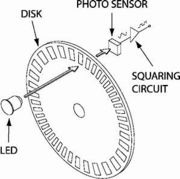
The optical encoder's disc is made of glass with transparent and opaque areas. A light source and photo detector array reads the optical pattern that results from the disc's position at any one time.
This code can be read by a controlling device, such as a microprocessor, to determine the angle of the shaft.
The absolute analog type produces a unique dual analog code that can be translated into an absolute angle of the shaft (by using a special algorithm).
[edit] Standard binary encoding

An example of a binary code, in an extremely simplified encoder with only three contacts, is shown below.
| Sector | Contact 1 | Contact 2 | Contact 3 | Angle |
|---|---|---|---|---|
| 1 | off | off | off | 0° to 45° |
| 2 | off | off | on | 45° to 90° |
| 3 | off | on | off | 90° to 135° |
| 4 | off | on | on | 135° to 180° |
| 5 | on | off | off | 180° to 225° |
| 6 | on | off | on | 225° to 270° |
| 7 | on | on | off | 270° to 315° |
| 8 | on | on | on | 315° to 360° |
In general, where there are n contacts, the number of distinct positions of the shaft is 2n. In this example, n is 3, so there are 2³ or 8 positions.
In the above example, the contacts produce a standard binary count as the disc rotates. However, this has the drawback that if the disc stops between two adjacent sectors, or the contacts are not perfectly aligned, it can be impossible to determine the angle of the shaft. To illustrate this problem, consider what happens when the shaft angle changes from 179.9° to 180.1° (from sector 4 to sector 5). At some instant, according to the above table, the contact pattern will change from off-on-on to on-off-off. However, this is not what happens in reality. In a practical device, the contacts are never perfectly aligned, and so each one will switch at a different moment. If contact 1 switches first, followed by contact 3 and then contact 2, for example, the actual sequence of codes will be
- off-on-on (starting position)
- on-on-on (first, contact 1 switches on)
- on-on-off (next, contact 3 switches off)
- on-off-off (finally, contact 2 switches off)
Now look at the sectors corresponding to these codes in the table. In order, they are 4, 8, 7 and then 5. So, from the sequence of codes produced, the shaft appears to have jumped from sector 4 to sector 8, then gone backwards to sector 7, then backwards again to sector 5, which is where we expected to find it. In many situations, this behaviour is undesirable and could cause the system to fail. For example, if the encoder were used in a robot arm, the controller would think that the arm was in the wrong position, and try to correct the error by turning it through 180°, perhaps causing damage to the arm.
[edit] Gray encoding

To avoid the above problem, Gray encoding is used. This is a system of binary counting in which adjacent codes differ in only one position. For the three-contact example given above, the Gray-coded version would be as follows.
| Sector | Contact 1 | Contact 2 | Contact 3 | Angle |
|---|---|---|---|---|
| 1 | off | off | off | 0° to 45° |
| 2 | off | off | on | 45° to 90° |
| 3 | off | on | on | 90° to 135° |
| 4 | off | on | off | 135° to 180° |
| 5 | on | on | off | 180° to 225° |
| 6 | on | on | on | 225° to 270° |
| 7 | on | off | on | 270° to 315° |
| 8 | on | off | off | 315° to 360° |
In this example, the transition from sector 4 to sector 5, like all other transitions, involves only one of the contacts changing its state from on to off or vice versa. This means that the sequence of incorrect codes shown in the previous illustration cannot happen here.
[edit] Single-track absolute rotary encoder
If the designer moves a contact to a different angular position (but at the same distance from the center shaft), then the corresponding "ring pattern" needs to be rotated the same angle to give the same output. If the most significant bit (the inner ring in Figure 1) is rotated enough, it exactly matches the next ring out. Since both rings are then identical, the inner ring can be omitted, and the sensor for that ring moved to the remaining, identical ring (but offset at that angle from the other sensor on that ring). Those two sensors on a single ring make a quadrature encoder.
For many years, Torsten Sillke and other mathematicians believed that it was impossible to encode position on a single track so that consecutive positions differed at only a single sensor, except for the two-sensor, one-track quadrature encoder. However, in 1996 Hiltgen, Paterson and Brandestini published a paper showing it was possible, with several examples. See Gray code for details.
[edit] Encoder output formats
In commercial absolute encoders there are several formats for transmission of absolute encoder data, including parallel binary, SSI, ISI, Profibus, CAN DeviceNet, CANopen, Endat and Hiperface, depending on the manufacturer of the device
[edit] Incremental rotary encoder
An incremental rotary encoder, also known as a quadrature encoder or a relative rotary encoder, has two outputs called quadrature outputs. They can be either mechanical or optical. In the optical type there are two gray coded tracks, while the mechanical type has two contacts that are actuated by cams on the rotating shaft. The mechanical types requires debouncing and are typically used as digital potentiometers on equipment including consumer devices. Most modern home and car stereos use mechanical rotary encoders for volume. Due to the fact the mechanical switches require debouncing, the mechanical type are limited in the rotational speeds they can handle. The incremental rotary encoder is the most widely used of all rotary encoders due to its low cost: only two sensors are required.
The fact that incremental encoders use only two sensors does not compromise their accuracy. One can find in the market incremental encoders with up to 10,000 counts per revolution, or more.
There can be an optional third output: reference, which happens once every turn. This is used when there is the need of an absolute reference, such as positioning systems.
The optical type is used when higher RPMs are encountered or a higher degree of precision is required.
Incremental encoders are used to track motion and can be used to determine position and velocity. This can be either linear or rotary motion. Because the direction can be determined, very accurate measurements can be made.
They employ two outputs called A & B which are called quadrature outputs as they are 90 degrees out of phase.
The state diagram:
|
|

The two output wave forms are 90 degrees out of phase, which is all that the quadrature term means. These signals are decoded to produce a count up pulse or a count down pulse. For decoding in software, the A & B outputs are read by software, either via an interrupt on any edge or polling, and the above table is used to decode the direction. For example if the last value was 00 and the current value is 01, the device has moved one half step in the clockwise direction. The mechanical types would be debounced first by requiring that the same (valid) value be read a certain number of times before recognizing a state change.
If the encoder is turning too fast, an invalid transition may occur, such as 00->11. There is no way to know which way the encoder turned; if it was 00->01->11, or 00->10->11.
If the encoder is turning even faster, a backward count may occur. Example: consider the 00->01->11->10 transition (3 steps forward). If the encoder is turning too fast, the system might read only the 00 and then the 10, which yields a 00->10 transition (1 step backward).
This same principle is used in ball mice to track whether the mouse is moving to the right/left or forward/backward.
Rotary sensors with a single output are not encoders and cannot sense direction, but can sense RPM. They are thus called tachometer sensors.
[edit] Sine wave encoder
A variation on the Incremental encoder is the Sinewave Encoder. Instead of producing two quadrature square waves, the outputs are quadrature sine waves (a Sine and a Cosine). By performing the arctangent function, arbitrary levels of resolution can be achieved.
[edit] Encoder technologies

Encoders may be implemented using a variety of technologies:
- Conductive tracks. A series of copper pads etched onto a PCB is used to encode the information. Contact brushes sense the conductive areas. This form of encoder is now rarely seen.
- Optical. This uses a light shining onto a photodiode through slits in a metal or glass disc. Reflective versions also exist. This is one of the most common technologies.
- Magnetic. Strips of magnetised material are placed on the rotating disc and are sensed by a Hall-effect sensor or magnetoresistive sensor. Hall effect sensors are also used to sense gear teeth directly, without the need for a separate encoder disc.
[edit] See also
Analogue devices that perform a similar function include the synchro, the resolver, the rotary variable differential transformer (RVDT) and the rotary potentiometer.
A Linear encoder is similar to a rotary encoder, but measures position in a straight line, rather than rotation. Linear encoders often use incremental encoding and are used in many machine tools.
[edit] External links
- "Choosing a code wheel: A detailed look at how encoders work" article by Steve Trahey 2008-03-25 describes "rotary encoders".
- "Encoders provide a sense of place" article by Jack Ganssle 2005-07-19 describes "nonlinear encoders".
- "Robot Encoders".
- "Encoders That are on the Market Today ".
- ProtoTalk.net - Understanding Quadrature Encoding - Covers details of rotary and quadrature encoding with a focus on robotic applications

