AT Attachment
From Wikipedia, the free encyclopedia
| AT Attachment with Packet Interface | ||||
|---|---|---|---|---|
|
||||
| Type | Internal storage device connector | |||
| Production history | ||||
| Designer | Western Digital, subsequently amended by many others | |||
| Designed | 1986 | |||
| Superseded by | Serial ATA (2003) | |||
| Specifications | ||||
| Hot pluggable | No | |||
| External | No | |||
| Width | 16 bits | |||
| Bandwidth | 16 MB/s originally later 33, 66, 100 and 133 MB/s |
|||
| Max. devices | 2 (master/slave) | |||
| Protocol | Parallel | |||
| Cable | 40 or 80 wires ribbon cable | |||
| Pins | 40 | |||
| Pin out | ||||
| Pin 1 | Reset | |||
| Pin 2 | Ground | |||
| Pin 3 | Data 7 | |||
| Pin 4 | Data 8 | |||
| Pin 5 | Data 6 | |||
| Pin 6 | Data 9 | |||
| Pin 7 | Data 5 | |||
| Pin 8 | Data 10 | |||
| Pin 9 | Data 4 | |||
| Pin 10 | Data 11 | |||
| Pin 11 | Data 3 | |||
| Pin 12 | Data 12 | |||
| Pin 13 | Data 2 | |||
| Pin 14 | Data 13 | |||
| Pin 15 | Data 1 | |||
| Pin 16 | Data 14 | |||
| Pin 17 | Data 0 | |||
| Pin 18 | Data 15 | |||
| Pin 19 | Ground | |||
| Pin 20 | Key or VCC_in | |||
| Pin 21 | DDRQ | |||
| Pin 22 | Ground | |||
| Pin 23 | I/O write | |||
| Pin 24 | Ground | |||
| Pin 25 | I/O read | |||
| Pin 26 | Ground | |||
| Pin 27 | IOCHRDY | |||
| Pin 28 | Cable select | |||
| Pin 29 | DDACK | |||
| Pin 30 | Ground | |||
| Pin 31 | IRQ | |||
| Pin 32 | No connect | |||
| Pin 33 | Addr 1 | |||
| Pin 34 | GPIO_DMA66_Detect | |||
| Pin 35 | Addr 0 | |||
| Pin 36 | Addr 2 | |||
| Pin 37 | Chip select 1P | |||
| Pin 38 | Chip select 3P | |||
| Pin 39 | Activity | |||
| Pin 40 | Ground | |||
AT Attachment (ATA) and AT Attachment Packet Interface (ATAPI) are interface standards for the connection of storage devices such as hard disks, solid-state drives, and CD-ROM drives in computers. The standard is maintained by X3/INCITS committee T13.
The current ATA/ATAPI standard is the result of a long history of incremental technical development. ATA/ATAPI is an evolution of the AT Attachment Interface, which was itself evolved in several stages from Western Digital's original Integrated Drive Electronics interface. As a result, many near-synonyms for ATA/ATAPI and its previous incarnations exist, including abbreviations such as IDE which are still in common informal use. With the market introduction of Serial ATA in 2003, the original ATA was retroactively renamed Parallel ATA (PATA).
Parallel ATA standards allow cable lengths up to only 18 inches (46 centimeters). Because of this length limit the technology normally appears as an internal computer storage interface. For many years ATA provided the most common and the least expensive interface for this application. By the beginning of 2007 it had largely been replaced by Serial ATA (SATA) in new systems.
[edit] History and terminology
The name of the standard was originally conceived as "PC/AT Attachment" as its primary feature was a direct connection to the 16-bit ISA bus introduced with the IBM PC/AT. The name was shortened to "AT Attachment" to avoid possible trademark issues. It is not spelled out as "Advanced Technology" anywhere in current or recent versions of the specification; it is simply "AT Attachment". Nevertheless, the term "Advanced Technology Attachment" is still in common use.
[edit] IDE and ATA-1
The first version of what is now called the ATA/ATAPI interface was developed by Western Digital under the name Integrated Drive Electronics (IDE). Together with Control Data Corporation (who manufactured the hard drive part) and Compaq Computer (into whose systems these drives would initially go), they developed the connector, the signalling protocols, and so on with the goal of remaining software compatible with the existing ST-506 hard drive interface.[1] The first such drives appeared in Compaq PCs in 1986.[2] [3]
The term Integrated Drive Electronics (IDE) refers not just to the connector and interface definition, but also to the fact that the drive controller is integrated into the drive, as opposed to a separate controller on or connected to the motherboard.[4] The integrated controller presented the drive to the host computer as an array of 512-byte blocks with a relatively simple command interface. This relieved the software in the host computer of the chores of stepping the disk head arm, moving the head arm in and out, and so on, as had to be done with earlier ST-506 and ESDI hard drives. All of these low-level details of the mechanical operation of the drive were now handled by the controller on the drive itself. This also eliminated the need to design a single controller that could handle many different types of drives, since the controller could be unique for the drive. The host need only ask for a particular sector, or block, to be read or written, and either accept the data from the drive or send the data to it.
The interface used by these IDE drives was standardized in 1994 as ANSI standard X3.221-1994, AT Attachment Interface for Disk Drives. After later versions of the standard were developed, this became known as "ATA-1".[5][6]
[edit] The second ATA interface
Originally, there was only one ATA controller in early PCs, which could support up to two hard drives. At the time in combination with the floppy drive, this was sufficient for most people, and eventually it became common to have two hard drives installed. When the CDROM was developed, many computers were unable to accept them due to already having two hard drives installed. Adding the CDROM would have required removal of one of the drives.
The solution was the addition of the second ATA interface, typically included as an expansion option on a sound card. It was included on the sound card because early business PCs did not include support for more than simple beeps from the internal speaker, and tuneful sound playback was considered unnecessary for early business software. When the CDROM was introduced, it was logical to also add digital audio to the computer at the same time. An older business PC could be upgraded in this manner to meet the Multimedia PC standard for early software packages that used sound and colorful video animation.
The second drive interface initially was not well-defined. It was first introduced with modified controller interfaces specific to certain CDROM drives such as Mitsumi, Sony or Panasonic[7], and it was common to find early sound cards with two or three separate connectors each designed to match a certain brand of CDROM drive. This evolved into the standard ATA interface for ease of cross-compatability, though the sound card ATA interface still usually supported only a single CDROM and not hard drives.
This second ATA interface on the sound card eventually evolved into the second motherboard ATA interface now included as a standard component in all PCs.
[edit] EIDE and ATA-2
In 1994, about the same time that the ATA-1 standard was adopted, Western Digital introduced drives under a slightly new name, Enhanced IDE (EIDE). These included most of the features of the forthcoming ATA-2 specification and several additional enhancements. Other manufacturers introduced their own variations of ATA-1 such as "Fast ATA" and "Fast ATA-2".
The new version of the ANSI standard, AT Attachment Interface with Extensions ATA-2 (X3.279-1996), was approved in 1996. It included most of the features of the manufacturer-specific variants.[8][9]
ATA-2 also was the first to note that devices other than hard drives could be attached to the interface:
3.1.7 Device: Device is a storage peripheral. Traditionally, a device on the ATA interface has been a hard disk drive, but any form of storage device may be placed on the ATA interface provided it adheres to this standard.
—from [9], page 2
[edit] ATAPI
As mentioned in the previous sections ATA was originally designed for and worked only with hard disks and devices that could emulate them. The introduction of ATAPI (ATA Packet Interface) by a group called the Small Form Factor committee allowed ATA to be used for a variety of other devices that require functions beyond those necessary for hard disks. For example, any removable media device needs a "media eject" command, and a way for the host to determine whether the media is present, and these were not provided in the ATA protocol.
The Small Form Factor committee approached this problem by defining ATAPI, the "ATA Packet Interface". ATAPI is actually a protocol allowing the ATA interface to carry SCSI commands and responses; therefore all ATAPI devices are actually "speaking SCSI" other than at the electrical interface. In fact, some early ATAPI devices were simply SCSI devices with an ATA/ATAPI to SCSI protocol converter added on. The SCSI commands and responses are embedded in "packets" (hence "ATA Packet Interface") for transmission on the ATA cable. This allows any device class for which a SCSI command set has been defined to be interfaced via ATA/ATAPI.
ATAPI devices are also "speaking ATA", as the ATA physical interface and protocol are still being used to send the packets. On the other hand, ATA hard drives and solid state drives do not use ATAPI.
ATAPI devices include CD-ROM and DVD-ROM drives, tape drives, and large-capacity floppy drives such as the Zip drive and SuperDisk drive.
The SCSI commands and responses used by each class of ATAPI device (CD-ROM, tape, etc.) are described in other documents or specifications specific to those device classes and are not within ATA/ATAPI or the T13 committee's purview.
ATAPI was adopted as part of ATA in INCITS 317-1998, AT Attachment with Packet Interface Extension (ATA/ATAPI-4).[10][11][12]
[edit] Current terminology
The terms "integrated drive electronics" (IDE), "enhanced IDE" and "EIDE" have come to be used interchangeably with ATA (now Parallel ATA). However the terms "IDE" and "EIDE" are at best imprecise. Every ATA drive is an "integrated drive electronics" drive, but not every "integrated drive electronics" drive is an ATA drive, as the term also correctly describes SCSI drives: They have the drive controllers on board and present the drive to the host as an array of blocks.
In addition there have been several generations of "EIDE" drives marketed, compliant with various versions of the ATA specification. An early "EIDE" drive might be compatible with ATA-2, while a later one with ATA-6.
Nevertheless a request for an "IDE" or "EIDE" drive from a computer parts vendor will almost always yield a drive that will work with modern systems' ATA interfaces.
Another common usage is to refer to the specification version by the fastest mode supported. For example, ATA-4 supported Ultra DMA modes 0 through 3, the latter providing a maximum transfer rate of 33 megabytes per second. ATA-4 drives are thus sometimes called "UDMA-33" drives. Similarly, ATA-6 introduced a maximum transfer speed of 100 megabytes per second, and some drives complying to this version of the standard are marketed as "PATA/100" drives.
[edit] Parallel ATA
With the introduction of Serial ATA around 2003, conventional ATA is sometimes referred to as Parallel ATA (P-ATA), referring to the method in which data travels over wires in this interface.
[edit] Drive size limitations
The original ATA specification used a 28-bit addressing mode, allowing for the addressing of 228 (268,435,456) sectors (blocks) of 512 bytes each, resulting in a maximum capacity of about 137 gigabytes[13]. (This is displayed by Windows operating systems as "128 GB".) However the BIOS in early PCs imposed smaller limits such as 8.46 GB, with a maximum of 1024 cylinders, 256 heads and 63 sectors, but this was not a limit imposed by the ATA interface.
ATA-6 introduced 48-bit addressing, increasing the limit to 144 petabytes. As a consequence, any ATA drive of capacity larger than 137 gigabytes must be an ATA-6 or later drive. Connecting such a drive to a host with an ATA-5 or earlier interface will limit the usable capacity to the maximum of the controller.
Some OSs, including Windows 2000 pre-SP4, disable 48-bit LBA by default, requiring the user to take extra steps to use the entire capacity of an ATA drive larger than 137 gigabytes. [14]
[edit] Parallel ATA interface
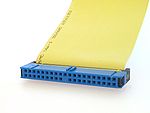
Until the introduction of Serial ATA, 40-pin connectors generally attached drives to a ribbon cable. Each cable has two or three connectors, one of which plugs into an adapter interfacing with the rest of the computer system. The remaining connector(s) plug into drives. Parallel ATA cables transfer data 16 bits at a time.
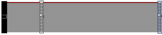
ATA's ribbon cables have had 40 wires for most of its history (44 conductors for the smaller form-factor version used for 2.5" drives), but an 80-wire version appeared with the introduction of the Ultra DMA/33 (UDMA) mode. All of the additional wires in the new cable are ground wires, interleaved with the previously defined wires to reduce the effects of capacitive coupling between neighboring signal wires, reducing crosstalk. Capacitive coupling is more of a problem at higher transfer rates, and this change was necessary to enable the 66 megabytes per second (MB/s) transfer rate of UDMA4 to work reliably. The faster UDMA5 and UDMA6 modes also require 80-conductor cables.
40 wire ribbon cable (top)
80 wire ribbon cable (bottom)
Though the number of wires doubled, the number of connector pins and the pinout remain the same as 40-conductor cables, and the external appearance of the connectors is identical. Internally the connectors are different; the connectors for the 80-wire cable connect a larger number of ground wires to a smaller number of ground pins, while the connectors for the 40-wire cable connect ground wires to ground pins one-for-one. 80-wire cables usually come with three differently colored connectors (blue - controller, gray - slave drive, and black - master drive) as opposed to uniformly colored 40-wire cable's connectors (all black). The gray connector on 80-conductor cables has pin 28 CSEL not connected; making it the slave position for drives configured cable select.
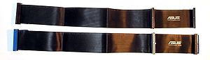
[edit] Using non-standard cables
The ATA standard has always specified a maximum cable length of 46 cm (18 inches), and flat cables with particular impedance and capacitance characteristics. It may be desirable to use alternative cables, e.g. to have longer cables when connecting drives within a large computer case or when mounting several physical drives into one computer, or to use rounded cables to improve airflow (cooling) inside the computer case. Such cables are widely available on the market and used successfully in most cases. However, the user must understand that they are outside the parameters set by the specifications and should be used with caution. The short standard cable length makes the use of parallel ATA for external devices impossible in most situations.
[edit] Pin 20
In the ATA standard, Pin 20 is defined as key and is not used. However, some flash memory disks can use pin 20 as VCC_in to power the disk without needing a special power cable[15].
[edit] Pin 28
Pin 28 of the gray (slave/middle) connector of an 80 conductor cable is not attached to any conductor of the cable. It is attached normally on the black (master drive end) and blue (motherboard end) connectors.
[edit] Pin 34
Pin 34 is connected to ground inside the blue connector of an 80 conductor cable but not attached to any conductor of the cable. It is attached normally on the gray and black connectors. See page 315 of [1].
[edit] Differences between connectors on 80 conductor cables

The image shows PATA connectors after removal of strain relief, cover, and cable. Pin one is at bottom left of the connectors, pin 2 is top left, etc., except that the lower image of the blue connector shows the view from the opposite side, and pin one is at top right.
Each contact comprises a pair of points which together pierce the insulation of the ribbon cable with such precision, they make a connection to the desired conductor without harming the insulation on the neighboring wires. The center row of contacts are all connected to the common ground bus and attached to the odd numbered conductors of the cable. The top row of contacts are the even-numbered sockets of the connector (mating with the even-numbered pins of the receptacle) and attach to every other even-numbered conductor of the cable. The bottom row of contacts are the odd-numbered sockets of the connector (mating with the odd-numbered pins of the receptacle) and attach to the remaining even-numbered conductors of the cable.
Note the connections to the common ground bus from sockets 2 (top left), 19 (center bottom row), 22, 24, 26, 30, and 40 on all connectors. Also note (enlarged detail, bottom, looking from the opposite side of the connector) that socket 34 of the blue connector does not contact any conductor but unlike socket 34 of the other two connectors, it does connect to the common ground bus. On the gray connector, note that socket 28 is completely missing, so that pin 28 of the drive attached to the gray connector will be open. On the black connector, sockets 28 and 34 are completely normal, so that pins 28 and 34 of the drive attached to the black connector will be connected to the cable. Pin 28 of the black drive reaches pin 28 of the host receptacle but not pin 28 of the gray drive, while pin 34 of the black drive reaches pin 34 of the gray drive but not pin 34 of the host. Instead, pin 34 of the host is grounded.
The standard dictates color-coded connectors for easy identification by both installer and cable maker. All three connectors are different from one another. The blue (host) connector has the socket for pin 34 connected to ground inside the connector but not attached to any conductor of the cable. Since the old 40 conductor cables do not ground pin 34, the presence of a ground connection indicates that an 80 conductor cable is installed. The wire for pin 34 is attached normally on the other types and is not grounded. Installing the cable backwards (with the black connector on the system board, the blue connector on the remote device and the gray connector on the center device) will ground pin 34 of the remote device and connect host pin 34 through to pin 34 of the center device. The gray center connector omits the connection to pin 28 but connects pin 34 normally, while the black end connector connects both pins 28 and 34 normally.
[edit] Multiple devices on a cable
If two devices attach to a single cable, one must be designated as device 0 (commonly referred to as master) and the other as device 1 (slave). This distinction is necessary to allow both drives to share the cable without conflict. The master drive is the drive that usually appears "first" to the computer's BIOS and/or operating system. On old BIOSes (486 era and older), the drives are often referred to by the BIOS as "C" for the master and "D" for the slave following the way DOS would refer to the active primary partitions on each.
The mode that a drive must use is often set by a jumper setting on the drive itself, which must be manually set to master or slave. If there is a single device on a cable, it should be configured as master. However, some hard drives have a special setting called single for this configuration (Western Digital, in particular). Also, depending on the hardware and software available, a single drive on a cable can work reliably even though configured as the slave drive (this configuration is most often seen when a CD ROM has a channel to itself).
[edit] Cable select
A drive mode called cable select was described as optional in ATA-1 and has come into fairly widespread use with ATA-5 and later. A drive set to "cable select" automatically configures itself as master or slave, according to its position on the cable. Cable select is controlled by pin 28. The host adapter grounds this pin; if a device sees that the pin is grounded, it becomes the master device; if it sees that pin 28 is open, the device becomes the slave device.
This setting is usually chosen by a jumper setting on the drive called "cable select", usually marked CS, which is separate to the "master" or "slave" setting.
Note that if two drives are configured as master and slave manually, this configuration does not need to correspond to their position on the cable. Pin 28 is only used to let the drives know their position on the cable; it is not used by the host when communicating with the drives.
With the 40-wire cable it was very common to implement cable select by simply cutting the pin 28 wire between the two device connectors; putting the slave device at the end of the cable, and the master on the "middle" connector. This arrangement eventually was standardized in later versions. If there is just one device on the cable, this results in an unused "stub" of cable, which is undesirable for physical convenience and electrical reasons. The stub causes signal reflections, particularly at higher transfer rates.
Starting with the 80-wire cable defined for use in ATAPI5/UDMA4, the master device goes at the end of the 18-inch (460 mm) cable (black connector), the middle-slave connector is gray, the blue connector goes onto the motherboard. So, if there is only one (master) device on the cable, there is no cable "stub" to cause reflections. Also, cable select is now implemented in the slave device connector, usually simply by omitting the contact from the connector body.
[edit] Master and slave clarification
Although they are in common use, the terms master and slave do not actually appear in current versions of the ATA specifications. The two devices are correctly referred to as device 0 (master) and device 1 (slave), respectively. It is a common myth that the controller on the master drive assumes control over the slave drive, or that the master drive may claim priority of communication over the other device on the channel. In fact, the drivers in the host operating system perform the necessary arbitration and serialization, and each drive's controller operates independently.
The terms "master" and "slave" have not been without controversy. In 2003, the County of Los Angeles, California, USA demanded that suppliers stop using the terms because the county found them unacceptable in light of its "cultural diversity and sensitivity." [2]
[edit] Serialized, overlapped, and queued operations
The parallel ATA protocols up through ATA-3 require that once a command has been given on an ATA interface, it must complete before any subsequent command may be given. Operations on the devices must be serialized—with only one operation in progress at a time—with respect to the ATA host interface. A useful mental model is that the host ATA interface is busy with the first request for its entire duration, and therefore can not be told about another request until the first one is complete. The function of serializing requests to the interface is usually performed by a device driver in the host operating system.
The ATA-4 and subsequent versions of the specification have included an "overlapped feature set" and a "queued feature set" as optional features. However, support for these is extremely rare in actual parallel ATA products and device drivers. By contrast, overlapped and queued operations have been common in other storage buses. In particular, tagged command queuing is characteristic of SCSI, this has long been seen as a major advantage of SCSI.
The Serial ATA standard has supported native command queueing since its first release, but it is an optional feature for both host-adapters and target-devices. Many less expensive PC motherboards do not support NCQ. Nearly all SATA/II hard drives sold today support NCQ, while very few removable (CD/DVD) drives do.
[edit] Two devices on one cable - speed impact
There are many debates about how much a slow device can impact the performance of a faster device on the same cable. There is an effect, but the debate is confused by the blurring of two quite different causes, called here "Lowest speed" and "One operation at a time".
[edit] "Lowest speed"
It is a common misconception that, if two devices of different speed capabilities are on the same cable, both devices' data transfers will be constrained to the speed of the slower device.
For all modern ATA host adapters this is not true, as modern ATA host adapters support independent device timing. This allows each device on the cable to transfer data at its own best speed. Even with older adapters without independent timing, this effect only applies to the data transfer phase of a read or write operation. This is usually the shortest part of a complete read or write operation. [16]
[edit] "One operation at a time"
This is caused by the omission of both overlapped and queued feature sets from most parallel ATA products. Only one device on a cable can perform a read or write operation at one time, therefore a fast device on the same cable as a slow device under heavy use will find it has to wait for the slow device to complete its task first.
However, most modern devices will report write operations as complete once the data is stored in its onboard cache memory, before the data is written to the (slow) magnetic storage. This allows commands to be sent to the other device on the cable, reducing the impact of the "one operation at a time" limit.
The impact of this on a system's performance depends on the application. For example, when copying data from an optical drive to a hard drive (such as during software installation), this effect probably doesn't matter: Such jobs are necessarily limited by the speed of the optical drive no matter where it is. But if the hard drive in question is also expected to provide good throughput for other tasks at the same time, it probably should not be on the same cable as the optical drive.
[edit] HDD Passwords and Security
The disk lock is a built-in security feature in the disk. It is part of the ATA specification, and thus not specific to any brand or device.
A disk always has two passwords: A User password and a Master password. Most disks support a Master Password Revision Code. Reportedly some disks can tell you if the Master password has been changed, or if it still the factory default. The revision code is word 92 in the IDENTIFY response. Reportedly on some disks a value of 0xFFFE means the Master password is unchanged. The standard does not distinguish this value.
A disk can be locked in two modes: High security mode or Maximum security mode. Bit 8 in word 128 of the IDENTIFY response tell you which mode your disk is in: 0 = High, 1 = Maximum.
In High security mode, you can unlock the disk with either the User or Master password, using the "SECURITY UNLOCK DEVICE" ATA command. There is an attempt limit, normally set to 5, after which you must power cycle or hard-reset the disk before you can attempt again. Also in High security mode the SECURITY ERASE UNIT command can be used with either the User or Master password.
In Maximum security mode, you cannot unlock the disk without the User password - the only way to get the disk back to a usable state is to issue the SECURITY ERASE PREPARE command, immediately followed by SECURITY ERASE UNIT. In Maximum security mode the SECURITY ERASE UNIT command requires the User password and will completely erase all data on the disk. The operation is rather slow, expect half an hour or more for big disks. (Word 89 in the IDENTIFY response indicates how long the operation will take.) [17] [18]
[edit] ATA standards versions, transfer rates, and features
The following table shows the names of the versions of the ATA standards and the transfer modes and rates supported by each. Note that the transfer rate for each mode (for example, 66.7 MB/s for UDMA4, commonly called "Ultra-DMA 66") gives its maximum theoretical transfer rate on the cable. This is simply two bytes multiplied by the effective clock rate, and presumes that every clock cycle is used to transfer end-user data. In practice, of course, protocol overhead reduces this value.
Congestion on the host bus to which the ATA adapter is attached may also limit the maximum burst transfer rate. For example, the maximum data transfer rate for conventional PCI bus is 133 MB/s, and this is shared among all active devices on the bus.
In addition, no ATA hard drives in 2005 existed that were capable of measured sustained transfer rates of above 80 MB/s. Furthermore, sustained transfer rate tests do not give realistic throughput expectations for most workloads: They use I/O loads specifically designed to encounter almost no delays from seek time or rotational latency. Hard drive performance under most workloads is limited first and second by those two factors; the transfer rate on the bus is a distant third in importance. Therefore, transfer speed limits above 66 MB/s really affect performance only when the hard drive can satisfy all I/O requests by reading from its internal cache — a very unusual situation, especially considering that such data is usually already buffered by the operating system.
As of 2008 mechanical hard disk drives can transfer data at up to 127 MB/s,[19] which is within the capabilities of the older PATA/133 specification. However, high-performance flash drives can transfer data at up to 201 MB/s.[20]
Only the Ultra DMA modes use CRC to detect errors in data transfer between the controller and drive. This is a 16 bit CRC, and it is used for data blocks only. Transmission of command and status blocks do not use the fast signaling methods that would necessitate CRC. For comparison, in Serial ATA, 32 bit CRC is used for both commands and data. [21]
| Standard | Other Names | Transfer Modes (MB/s) | Maximum disk size | Other New Features | ANSI Reference |
|---|---|---|---|---|---|
| pre-ATA | IDE | PIO 0 | 2.1 GB | 22-bit logical block addressing (LBA) | - |
| ATA-1 | ATA, IDE | PIO 0, 1, 2 (3.3, 5.2, 8.3) Single-word DMA 0, 1, 2 (2.1, 4.2, 8.3) Multi-word DMA 0 (4.2) |
137 GB | 28-bit logical block addressing (LBA) | X3.221-1994 (obsolete since 1999) |
| ATA-2 | EIDE, Fast ATA, Fast IDE, Ultra ATA |
PIO 3, 4: (11.1, 16.6) Multi-word DMA 1, 2 (13.3, 16.6) |
PCMCIA connector | X3.279-1996 (obsolete since 2001) |
|
| ATA-3 | EIDE | Single-word DMA modes dropped [3] | S.M.A.R.T., Security, 44 pin connector for 2.5" drives | X3.298-1997 (obsolete since 2002) |
|
| ATA/ATAPI-4 | ATA-4, Ultra ATA/33 | Ultra DMA 0, 1, 2 (16.7, 25.0, 33.3) aka UDMA/33 |
AT Attachment Packet Interface (ATAPI) (support for CD-ROM, tape drives etc.), Optional overlapped and queued command set features, Host Protected Area (HPA), CompactFlash Association (CFA) feature set for solid state drives | NCITS 317-1998 | |
| ATA/ATAPI-5 | ATA-5, Ultra ATA/66 | Ultra DMA 3, 4 (44.4, 66.7) aka UDMA/66 |
80-wire cables; CompactFlash connector | NCITS 340-2000 | |
| ATA/ATAPI-6 | ATA-6, Ultra ATA/100 | UDMA 5 (100) aka UDMA/100 |
144 PB | 48-bit LBA, Device Configuration Overlay (DCO), Automatic Acoustic Management |
NCITS 361-2002 |
| ATA/ATAPI-7 | ATA-7, Ultra ATA/133 | UDMA 6 (133) aka UDMA/133 SATA/150 |
SATA 1.0, Streaming feature set, long logical/physical sector feature set for non-packet devices | NCITS 397-2005 (vol 1) | |
| ATA/ATAPI-8 | ATA-8 | — | Hybrid drive featuring non-volatile cache to speed up critical OS files | In progress |
[edit] Related standards, features, and proposals
[edit] ATAPI Removable Media Device (ARMD)
ATAPI devices with removable media, other than CD and DVD drives, are classified as ARMD (ATAPI Removable Media Device) and can appear as either a super-floppy (non-partitioned media) or a hard drive (partitioned media) to the operating system. These can be supported as bootable devices by a BIOS complying with the ATAPI Removable Media Device BIOS Specification[22], originally developed by Compaq Computer Corporation and Phoenix Technologies. It specifies provisions in the BIOS of a personal computer to allow the computer to be bootstrapped from devices such as Zip drives, Jaz drives, SuperDisk (LS-120) drives, and similar devices.
These devices have removable media like floppy disk drives, but capacities more commensurate with hard drives, and programming requirements unlike either. Due to limitations in the floppy controller interface most of these devices were ATAPI devices, connected to one of the host computer's ATA interfaces, similarly to a hard drive or CD-ROM device. However, existing BIOS standards did not support these devices. An ARMD-compliant BIOS allows these devices to booted from and used under the operating system without requiring device-specific code in the OS.
A BIOS implementing ARMD allows the user to include ARMD devices in the boot search order. Usually an ARMD device is configured earlier in the boot order than the hard drive. Similarly to a floppy drive, if bootable media is present in the ARMD drive, the BIOS will boot from it; if not, the BIOS will continue in the search order, usually with the hard drive last.
There are two variants of ARMD, ARMD-FDD and ARMD-HDD. Originally ARMD caused the devices to appear as a sort of "very large floppy drive," either the primary floppy drive device 00h or the secondary device 01h. Some operating systems required code changes to support "floppy disks" with capacities far larger than any actual floppy drive. Also, floppy drive emulation proved to be unsuitable for certain devices such as Iomega Zip drives. Later the ARMD-HDD, ARMD-"Hard disk device", variant was developed to address these issues. Under ARMD-HDD, an ARMD device appears to the BIOS and the operating system as a hard drive.
[edit] ATA over Ethernet
In August 2004, Sam Hopkins and Brantley Coile of Coraid specified a lightweight ATA-over-Ethernet protocol to carry ATA commands over Ethernet instead of directly connecting them to a PATA host adapter. This permitted the established block protocol to be reused in Storage area network applications.
[edit] See also
- Master-slave (technology)
- Advanced Host Controller Interface (AHCI)
- List of device bandwidths
- CE-ATA Consumer Electronics (CE) ATA [4]
- Serial ATA
- FATA (hard drive)
- SCSI
- BIOS for BIOS Boot Specification (BBS)
- INT 13 for BIOS Enhanced Disk Drive Specification (SFF-8039i)
- ATA-over-Ethernet (AoE)
[edit] References
- ^ "IDE drives on-board controllers are configured to appear to the computer like standard ST506 drives" "System Architecture: a look at hard drives". http://www.ackadia.com/computer/system-architecture/system-architecture-harddrive.php. Retrieved on 2008-07-25.
- ^ Charles M. Kozierok (2001-04-17). "The PC Guide: Overview and History of the IDE/ATA Interface". http://www.pcguide.com/ref/hdd/if/ide/over.htm. Retrieved on 2008-08-23.
- ^ Gene Milligan (2005-12-18). "The History of CAM ATA". http://www.ata-atapi.com/histcam.html. Retrieved on 2008-08-27.
- ^ The interface cards used to connect a parallel ATA drive to, for example, a PCI slot are not drive controllers, they are merely bridges between the host bus and the ATA interface.
- ^ Charles M. Kozierok (2001-04-17). "The PC Guide: ATA (ATA-1)". http://www.pcguide.com/ref/hdd/if/ide/stdATA-c.html. Retrieved on 2008-08-23.
- ^ [|Technical Committee T13 AT Attachment] (1994). AT Attachment Interface for Disk Drives (ATA-1). Global Engineering Documents.
- ^ Creative Labs sound card documentation showing diagram with custom Mitsumi, Sony, and Panasonic CDROM drive connectors http://stason.org/TULARC/pc/sound-cards-multimedia/CREATIVE-LABS-INC-Sound-card-16-BIT-AUDIO-CARD-PAN.html
- ^ Charles M. Kozierok (2001-04-17). "The PC Guide: ATA (ATA-2)". http://www.pcguide.com/ref/hdd/if/ide/stdATA2-c.html. Retrieved on 2008-08-23.
- ^ a b [|Technical Committee T13 AT Attachment] (1996). AT Attachment Interface with Extensions (ATA-2). Global Engineering Documents.
- ^ Charles M. Kozierok (2001-04-17). "The PC Guide: SFF-8020 / ATA Packet Interface (ATAPI)". http://www.pcguide.com/ref/hdd/if/ide/stdATAPI-c.html. Retrieved on 2008-08-23.
- ^ Charles M. Kozierok (2001-04-17). "The PC Guide: ATA/ATAPI-4". http://www.pcguide.com/ref/hdd/if/ide/stdATA4-c.html. Retrieved on 2008-08-23.
- ^ [|Technical Committee T13 AT Attachment] (1998). AT Attachment with Packet Interface Extension (ATA/ATAPI-4). Global Engineering Documents.
- ^ Disk-based memory (hard drives), solid state disk devices such as USB drives and CompactFlash cards, DVD-based storage, bus speeds, and network speeds, are specified using decimal meanings for K (10001), M (10002), G (10003), ...
- ^ "Large Disk HOWTO: History of BIOS and IDE limits". http://tldp.org/HOWTO/Large-Disk-HOWTO-4.html.
- ^ Welcome to Transcend website
- ^ Charles M. Kozierok (2001-04-17). "Independent Master/Slave Device Timing". The PC Guide. http://www.pcguide.com/ref/hdd/if/ide/confTiming-c.html. Retrieved on 2008-08-08.
- ^ Rockbox - Unlocking a password protected harddisk
- ^ c't 8/2005, S. 172: Hard Disk Security
- ^ Patrick Schmid and Achim Roos (2008-11-24). "Tom’s Winter 2008 Hard Drive Guide Throughput and Interface Performance". tomshardware.com. http://www.tomshardware.com/reviews/hdd-terabyte-1tb,2077-11.html. Retrieved on 2009-03-15.
- ^ Patrick Schmid and Achim Roos (2009-01-28). "Six New SSDs: Can Intel Be Dethroned? Throughput, Interface Performance". tomshardware.com. http://www.tomshardware.com/reviews/ssd-hdd-flash,2127-9.html. Retrieved on 2009-03-15.
- ^ "serialata - a comparison with ultra ata technology". http://www.serialata.org/docs/serialata%20-%20a%20comparison%20with%20ultra%20ata%20technology.pdf. www.serialata.org
- ^ http://www.phoenix.com/NR/rdonlyres/EDD1AAA0-177E-4024-A0B1-E4BD06B673F7/0/specsatapi.pdf
[edit] External links
- Overview and History of the IDE/ATA Interface, circa 2000
- ATA/ATAPI history
- Enhanced IDE/Fast-ATA/ATA-2 FAQ
- ATA/ATAPI FAQ
- Connecting IDE Hard Drives from mikeshardware.com
- Hard Drive Size Barriers
- T13 Technical Standards Group
- Computer Interface Help and Information
- How to solve one well known dma-mode problem in WinXP
- Seagate support using Cable Select
- PC Guide - Configuration Using Cable Select
- Unixwiz - Using IDE Cable Select
- U.S. Patent 6523071 discusses detailed use of pin 34 by host to distinguish 40 and 80 conductor cables
- Draft copy of ATA-ATAPI-5 standard, revision 3 dated 29 February 2000

