Milling machine
From Wikipedia, the free encyclopedia


|
|
This article includes a list of references or external links, but its sources remain unclear because it lacks inline citations. Please improve this article by introducing more precise citations where appropriate. (October 2008) |
A milling machine is a machine tool used for the shaping of metal and other solid materials. Milling machines exist in two basic forms: horizontal and vertical, which terms refer to the orientation of the cutting tool spindle. Unlike a drill press, in which the workpiece is held stationary and the drill is moved vertically to penetrate the material, milling also involves movement of the workpiece against the rotating cutter, the latter which is able to cut on its flanks as well as its tip. Workpiece and cutter movement are precisely controlled to less than 0.001 inches (.025 millimeters), usually by means of precision ground slides and leadscrews or analogous technology. Milling machines may be manually operated, mechanically automated, or digitally automated via computer numerical control (CNC).
Milling machines can perform a vast number of operations, some very complex, such as slot and keyway cutting, planing, drilling, diesinking, rebating, routing, etc. Cutting fluid is often pumped to the cutting site to cool and lubricate the cut, and to sluice away the resulting swarf.
Contents |
[edit] Types of milling machines
There are many ways to classify milling machines, depending on which criteria are the focus:
| Criterion | Example classification scheme | Comments |
|---|---|---|
| Control | Manual; Mechanically automated via cams; Digitally automated via NC/CNC |
In the CNC era, a very basic distinction is manual versus CNC. Among manual machines, a worthwhile distinction is non-DRO-equipped versus DRO-equipped |
| Control (specifically among CNC machines) | Number of axes (e.g., 3-axis, 4-axis, or more); Within this scheme, also:
|
|
| Spindle axis orientation | Vertical versus horizontal; Turret versus non-turret |
Among vertical mills, "Bridgeport-style" is a whole class of mills inspired by the Bridgeport original |
| Purpose | General-purpose versus special-purpose or single-purpose | |
| Purpose | Toolroom machine versus production machine | Overlaps with above |
| Purpose | "Plain" versus "universal" | A distinction whose meaning evolved over decades as technology progressed, and overlaps with other purpose classifications above; more historical interest than current |
| Size | Micro, mini, benchtop, standing on floor, large, very large, gigantic | |
| Power source | Line-shaft-drive versus individual electric motor drive | Most line-shaft-drive machines, ubiquitous circa 1880-1930, have been scrapped by now |
| Hand-crank-power versus electric | Hand-cranked not used in industry but suitable for hobbyist micromills |
[edit] Comparing vertical with horizontal
In the vertical mill the spindle axis is vertically oriented. Milling cutters are held in the spindle and rotate on its axis. The spindle can generally be extended (or the table can be raised/lowered, giving the same effect), allowing plunge cuts and drilling. There are two subcategories of vertical mills: the bedmill and the turret mill. Turret mills, like the ubiquitous Bridgeport, are generally smaller than bedmills, and are considered by some to be more versatile. In a turret mill the spindle remains stationary during cutting operations and the table is moved both perpendicular to and parallel to the spindle axis to accomplish cutting. In the bedmill, however, the table moves only perpendicular to the spindle's axis, while the spindle itself moves parallel to its own axis. Also of note is a lighter machine, called a mill-drill. It is quite popular with hobbyists, due to its small size and lower price. These are frequently of lower quality than other types of machines, however.
A horizontal mill has the same sort of x–y table, but the cutters are mounted on a horizontal arbor (see Arbor milling) across the table. A majority of horizontal mills also feature a +15/-15 degree rotary table that allows milling at shallow angles. While endmills and the other types of tools available to a vertical mill may be used in a horizontal mill, their real advantage lies in arbor-mounted cutters, called side and face mills, which have a cross section rather like a circular saw, but are generally wider and smaller in diameter. Because the cutters have good support from the arbor, quite heavy cuts can be taken, enabling rapid material removal rates. These are used to mill grooves and slots. Plain mills are used to shape flat surfaces. Several cutters may be ganged together on the arbor to mill a complex shape of slots and planes. Special cutters can also cut grooves, bevels, radii, or indeed any section desired. These specialty cutters tend to be expensive. Simplex mills have one spindle, and duplex mills have two. It is also easier to cut gears on a horizontal mill.

Here is a video showing a Vertical Milling Machine. It shows the differences and options of a milling machine. http://www.youtube.com/watch?v=Sk2yLODbfjo
[edit] Other milling machine variants and terminology
- Box or column mills are very basic hobbyist bench-mounted milling machines that feature a head riding up and down on a column or box way.
- Turret or vertical ram mills are more commonly referred to as Bridgeport-type milling machines. The spindle can be aligned in many different positions for a very versatile, if somewhat less rigid machine.
- Knee mill or knee-and-column mill refers to any milling machine whose x-y table rides up and down the column on a vertically adjustable knee. This includes Bridgeports.
- C-Frame mills are larger, industrial production mills. They feature a knee and fixed spindle head that is only mobile vertically. They are typically much more powerful than a turret mill, featuring a separate hydraulic motor for integral hydraulic power feeds in all directions, and a twenty to fifty horsepower motor. Backlash eliminators are almost always standard equipment. They use large NMTB 40 or 50 tooling. The tables on C-frame mills are usually 18" by 68" or larger, to allow multiple parts to be machined at the same time.
- Planer-style mills are large mills built in the same configuration as planers except with a milling spindle instead of a planing head. This term is growing dated as planers themselves are largely a thing of the past.
- Bed mill refers to any milling machine where the spindle is on a pendant that moves up and down to move the cutter into the work. These are generally more rigid than a knee mill.
- Ram type mill refers to a mill that has a swiveling cutting head mounted on a sliding ram. The spindle can be oriented either vertically or horizontally, or anywhere in between. Van Norman specialized in ram type mills through most of the 20th century, but since the advent of CNC machines ram type mills are no longer made.
- Jig borers are vertical mills that are built to bore holes, and very light slot or face milling. They are typically bed mills with a long spindle throw. The beds are more accurate, and the handwheels are graduated down to .0001" for precise hole placement.
- Horizontal boring mills are large, accurate bed horizontal mills that incorporate many features from various machine tools. They are predominantly used to create large manufacturing jigs, or to modify large, high precision parts. They have a spindle stroke of several (usually between four and six) feet, and many are equipped with a tailstock to perform very long boring operations without losing accuracy as the bore increases in depth. A typical bed would have X and Y travel, and be between three and four feet square with a rotary table or a larger rectangle without said table. The pendant usually has between four and eight feet in vertical movement. Some mills have a large (30" or more) integral facing head. Right angle rotary tables and vertical milling attachments are available to further increase productivity.
- Floor mills have a row of rotary tables, and a horizontal pendant spindle mounted on a set of tracks that runs parallel to the table row. These mills have predominantly been converted to CNC, but some can still be found (if one can even find a used machine available) under manual control. The spindle carriage moves to each individual table, performs the machining operations, and moves to the next table while the previous table is being set up for the next operation. Unlike any other kind of mill, floor mills have floor units that are entirely movable. A crane will drop massive rotary tables , X-Y tables , and the like into position for machining, allowing the largest and most complex custom milling operations to take place.
[edit] Computer numerical control

Most CNC milling machines (also called machining centers) are computer controlled vertical mills with the ability to move the spindle vertically along the Z-axis. This extra degree of freedom permits their use in diesinking, engraving applications, and 2.5D surfaces such as relief sculptures. When combined with the use of conical tools or a ball nose cutter, it also significantly improves milling precision without impacting speed, providing a cost-efficient alternative to most flat-surface hand-engraving work.

CNC machines can exist in virtually any of the forms of manual machinery, like horizontal mills. The most advanced CNC milling-machines, the 5-axis machines, add two more axes in addition to the three normal axes (XYZ). Horizontal milling machines also have a C or Q axis, allowing the horizontally mounted workpiece to be rotated, essentially allowing asymmetric and eccentric turning. The fifth axis (B axis) controls the tilt of the tool itself. When all of these axes are used in conjunction with each other, extremely complicated geometries, even organic geometries such as a human head can be made with relative ease with these machines. But the skill to program such geometries is beyond that of most operators. Therefore, 5-axis milling machines are practically always programmed with CAM.
With the declining price of computers, free operating systems such as Linux, and open source CNC software, the entry price of CNC machines has plummeted. For example, Sherline, Prazi, and others make desktop CNC milling machines that are affordable by hobbyists.

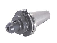
[edit] Milling machine tooling
There is some degree of standardization of the tooling used with CNC Milling Machines and to a much lesser degree with manual milling machines.
CNC Milling machines will nearly always use SK (or ISO), CAT, BT or HSK tooling. SK tooling is the most common in Europe, while CAT tooling, sometimes called V-Flange Tooling, is the oldest variation and is probably still the most common in the USA. CAT tooling was invented by Caterpillar Inc. of Peoria, Illinois in order to standardize the tooling used on their machinery. CAT tooling comes in a range of sizes designated as CAT-30, CAT-40, CAT-50, etc. The number refers to the Association for Manufacturing Technology (formerly the National Machine Tool Builders Association (NMTB)) Taper size of the tool.
An improvement on CAT Tooling is BT Tooling, which looks very similar and can easily be confused with CAT tooling. Like CAT Tooling, BT Tooling comes in a range of sizes and uses the same NMTB body taper. However, BT tooling is symmetrical about the spindle axis, which CAT tooling is not. This gives BT tooling greater stability and balance at high speeds. One other subtle difference between these two toolholders is the thread used to hold the pull stud. CAT Tooling is all Imperial thread and BT Tooling is all Metric thread. Note that this affects the pull stud only, it does not affect the tool that they can hold, both types of tooling are sold to accept both Imperial and metric sized tools.
SK and HSK tooling, sometimes called "Hollow Shank Tooling", is much more common in Europe where it was invented than it is in the United States. It is claimed that HSK tooling is even better than BT Tooling at high speeds. The holding mechanism for HSK tooling is placed within the (hollow) body of the tool and, as spindle speed increases, it expands, gripping the tool more tightly with increasing spindle speed. There is no pull stud with this type of tooling.
The situation is quite different for manual milling machines — there is little standardization. Newer and larger manual machines usually use NMTB tooling. This tooling is somewhat similar to CAT tooling but requires a drawbar within the milling machine. Furthermore, there are a number of variations with NMTB tooling that make interchangeability troublesome.
Two other tool holding systems for manual machines are worthy of note: They are the R8 collet and the Morse Taper #2 collet. Bridgeport Machines of Bridgeport, Connecticut so dominated the milling machine market for such a long time that their machine "The Bridgeport" is virtually synonymous with "Manual milling machine." The bulk of the machines that Bridgeport made from about 1965 onward used an R8 collet system. Prior to that, the bulk of the machines used a Morse Taper #2 collet system.
As an historical footnote: Bridgeport is now owned by Hardinge Brothers of Elmira, New York.
[edit] History
[edit] 1810s-1830s
Milling machines evolved from the practice of rotary filing—that is, running a circular cutter with file-like teeth in the headstock of a lathe. Both rotary filing and later true milling were developed in order to reduce the time and effort spent on hand-filing. The full, true story of the milling machine's development will probably never be known, because much of the early development took place in individual shops where generally no one was taking down records for posterity. However, the broad outlines are known. Rotary filing long predated milling. A rotary file by Jacques de Vaucanson, circa 1760, is well known. It is clear that milling machines as a distinct class of machine tool (separate from lathes running rotary files) first appeared between 1814 and 1818. Joseph W. Roe, a respected founding father of machine tool historians, credited Eli Whitney with producing the first true milling machine. However, subsequent scholars, including Robert S. Woodbury and others, suggest that just as much credit belongs to various other inventors, including Robert Johnson, Simeon North, Captain John H. Hall, and Thomas Blanchard. (Several of the men mentioned above are sometimes described on the internet as "the inventor of the first milling machine" or "the inventor of interchangeable parts". Such claims are oversimplified, as these technologies evolved over time among many people.) The two federal armories of the U.S. (Springfield and Harpers Ferry) and the various private armories and inside contractors that shared turnover of skilled workmen with them were the centers of earliest development of true milling machines (as distinct from lathe headstocks tooled up for rotary filing).
James Nasmyth built a milling machine very advanced for its time between 1829 and 1831. It was tooled to mill the six sides of a hex nut that was mounted in a six-way indexing fixture.
A milling machine built and used in the shop of Gay & Silver (aka Gay, Silver, & Co) in the 1830s was influential because it employed a better method of vertical positioning than earlier machines. For example, Whitney's machine (the one that Roe considered the very first) and others did not make provision for vertical travel of the knee. Evidently the workflow assumption behind this was that the machine would be set up with shims, vise, etc. for a certain part design and successive parts would not require vertical adjustment (or at most would need only shimming). This indicates that the earliest way of thinking about milling machines was as production machines, not toolroom machines.
[edit] 1840s-1860
Some of the key men in milling machine development during this era included Frederick W. Howe, Francis A. Pratt, Elisha K. Root, and others. (These same men during the same era were also busy developing the state of the art in turret lathes. Howe's experience at Gay & Silver in the 1840s acquainted him with early versions of both machine tools. His machine tool designs were later built at Robbins & Lawrence, the Providence Tool Company, and Brown & Sharpe.) The most successful milling machine design to emerge during this era was the Lincoln miller, which rather than being a specific make and model of machine tool is truly a family of related tools built by various companies over several decades. It took its name from the first company to put one on the market, George S. Lincoln & Company.
During this era there was a continued blind spot in milling machine design, as various designers failed to develop a truly simple and effective means of providing slide travel in all three of the archetypal milling axes (X, Y, and Z—or as they were known in the past, longitudinal, traverse, and vertical). Vertical positioning ideas were either absent or underdeveloped.
[edit] 1860s

In 1861, Frederick W. Howe, while working for the Providence Tool Company, asked Joseph R. Brown of Brown & Sharpe for a solution to the problem of milling spirals, such as the flutes of twist drills. These were filed by hand at the time. Brown designed a "universal milling machine" that, starting from its first sale in March 1862, was wildly successful. It solved the problem of 3-axis (XYZ) travel much more elegantly than had been done in the past, and it allowed for the milling of spirals using an indexing head fed in coordination with the table feed. The term "universal" was applied to it because it was ready for any kind of work and was not as limited in application as previous designs. (Howe had designed a "universal miller" in 1852, but Brown's of 1861 is the one considered groundbreakingly successful.)
Brown also developed and patented (1864) the design of formed milling cutters in which successive sharpenings of the teeth do not disturb the geometry of the form.
The advances of the 1860s opened the floodgates and ushered in modern milling practice.
[edit] 1870s-1930s
Two firms which most dominated the milling machine field during these decades were Brown & Sharpe and the Cincinnati Milling Machine Company. However, hundreds of other firms built milling machines during this time, and many were significant in one way or another. The archetypal workhorse milling machine of the late 19th and early 20th centuries was a heavy knee-and-column horizontal-spindle design with power table feeds, indexing head, and a stout overarm to support the arbor.
A. L. De Leeuw of the Cincinnati Milling Machine Company is credited with applying scientific study to the design of milling cutters, leading to modern practice with larger, more widely spaced teeth.
Around the end of World War I, machine tool control advanced in various ways that laid the groundwork for later CNC technology. The jig borer popularized the ideas of coordinate dimensioning (dimensioning of all locations on the part from a single reference point); working routinely in "tenths" (ten-thousandths of an inch, 0.0001") as an everyday machine capability; and using the control to go straight from drawing to part, circumventing jig-making. In 1920 the new tracer design of J.C. Shaw was applied to Keller tracer milling machines for die-sinking via the three-dimensional copying of a template. This made diesinking faster and easier just as dies were in higher demand than ever before, and was very helpful for large steel dies such as those used to stamp sheets in automobile manufacturing. Such machines translated the tracer movements to input for servos that worked the machine leadscrews or hydraulics. They also spurred the development of antibacklash leadscrew nuts. All of the above concepts were new in the 1920s but would become routine in the NC/CNC era. By the 1930s, incredibly large and advanced milling machines existed, such as the Cincinnati Hydro-Tel, that presaged today's CNC mills in every respect except the CNC control itself.
[edit] 1940s-1970s
By 1940, automation via cams, such as in screw machines and automatic chuckers, had already been very well developed for decades. By the close of World War II, many additional ideas involving servomechanisms were in the air. These ideas, which soon were combined with the emerging technology of digital computers, transformed machine tool control very deeply. The details (which are beyond the scope of this article) have evolved immensely with every passing decade since World War II.
During the 1950s, numerical control (NC) made its appearance.
During the 1960s and 1970s, NC evolved into CNC, data storage and input media evolved, computer processing power and memory capacity steadily increased, and NC and CNC machine tools gradually disseminated from the level of huge corporations to the level of medium-sized corporations.
[edit] 1980s-present
Computers and CNC machine tools continue to develop rapidly. The PC revolution has a great impact on this development. By the late 1980s small machine shops had desktop computers and CNC machine tools. After that hobbyists began obtaining CNC mills and lathes.
[edit] See also
[edit] References
[edit] Further reading
- Hounshell, David A. (1984), From the American system to mass production, 1800-1932: The development of manufacturing technology in the United States, Baltimore, Maryland, USA: Johns Hopkins University Press, LCCN 83-016269, ISBN 978-0-8018-2975-8.
- Noble, David F. (1984), Forces of production: a social history of industrial automation, New York: Knopf, LCCN 83-048867, ISBN 978-0-394-51262-4.
- Roe, Joseph Wickham (1916), English and American Tool Builders, New Haven, Connecticut, USA: Yale University Press, LCCN 16-011753. Reprinted by McGraw-Hill, New York and London, 1926 (LCCN 27-024075); and by Lindsay Publications, Inc., Bradley, IL, USA (ISBN 978-0-917914-73-7). Also available online via Google Book Search.
- Rolt, L.T.C. (1965), A Short History of Machine Tools, Cambridge, Massachusetts, USA: MIT Press, LCCN 65-12439. Co-edition published as Rolt, L.T.C. (1965), Tools for the Job: a Short History of Machine Tools, London: B. T. Batsford, LCCN 65-080822.
- Woodbury, Robert S. (1972), History of the Milling Machine. In Studies in the History of Machine Tools, Cambridge, Massachusetts, USA, and London, England: MIT Press, LCCN 72-006354, ISBN 978-0-262-73033-4. First published alone as a monograph in 1960.
[edit] External links
| Wikimedia Commons has media related to: Milling machines |
|
||||||||

