Data flow diagram
From Wikipedia, the free encyclopedia

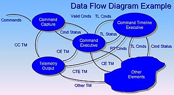
A data-flow diagram (DFD) is a graphical representation of the "flow" of data through an information system. It differs from the flowchart as it shows the data flow instead of the control flow of the program.
A data-flow diagram can also be used for the visualization of data processing (structured design).
Contents |
[edit] Overview
It is common practice to draw a context-level data flow diagram first which shows the interaction between the system and outside entities. The DFD is designed to show how a system is divided into smaller portions and to highlight the flow of data between those parts. This context-level data-flow diagram is then "exploded" to show more detail of the system being modeled.
Data-flow diagrams were invented by Larry Constantine, the original developer of structured design,[2] based on Martin and Estrin's "data-flow graph" model of computation.
Data-flow diagrams (DFDs) are one of the three essential perspectives of the structured-systems analysis and design method SSADM. The sponsor of a project and the end users will need to be briefed and consulted throughout all stages of a system's evolution. With a data-flow diagram, users are able to visualize how the system will operate, what the system will accomplish, and how the system will be implemented. The old system's dataflow diagrams can be drawn up and compared with the new system's data-flow diagrams to draw comparisons to implement a more efficient system. Data-flow diagrams can be used to provide the end user with a physical idea of where the data they input ultimately has an effect upon the structure of the whole system from order to dispatch to report. How any system is developed can be determined through a data-flow diagram.
Developing a data-flow diagram helps in identifying the transaction data in the data model.
There are different notations to draw data-flow diagrams, defining different visual representations for processes, data stores, data flow, and external entities.[3]
[edit] Developing a data-flow diagram
[edit] Top-Down Approach
- The system designer makes "a context level DFD" or Level 0, which shows the "interaction" (data flows) between "the system" (represented by one process) and "the system environment" (represented by terminators).
- The system is "decomposed in lower-level DFD (Level 1)" into a set of "processes, data stores, and the data flows between these processes and data stores".
- Each process is then decomposed into an "even-lower-level diagram containing its subprocesses".
- This approach "then continues on the subsequent subprocesses", until a necessary and sufficient level of detail is reached which is called the primitive process (aka chewable in one bite).
DFD is also a virtually designable diagram that technically or diagrammatically describes the inflow and outflow of data or information that is provided by the external entity.
[edit] Event Partitioning Approach
Event partitioning was described by Edward Yourdon in Just Enough Structured Analysis.[4]
- Construct detailed data-flow diagram.
- The list of all events is made.
- For each event a process is constructed.
- Each process is linked (with incoming data flows) directly with other processes or via data stores, so that it has enough information to respond to a given event.
- The reaction of each process to a given event is modeled by an outgoing data flow.
[edit] Data flow diagram levels
[edit] Context Level Diagram
This level shows the overall context of the system and its operating environment and shows the whole system as just one process. It does not usually show data stores, unless they are "owned" by external systems, e.g. are accessed by but not maintained by this system, however, these are often shown as external entities.[5]
[edit] Level 1 (High Level Diagram)
This level (level 1) shows all processes at the first level of numbering, data stores, external entities and the data flows between them. The purpose of this level is to show the major high-level processes of the system and their interrelation. A process model will have one, and only one, level-1 diagram. A level-1 diagram must be balanced with its parent context level diagram, i.e. there must be the same external entities and the same data flows, these can be broken down to more detail in the level 1, e.g. the "enquiry" data flow could be spilt into "enquiry request" and "enquiry results" and still be valid.[5]
[edit] Level 2 (Low Level Diagram)
This level is a decomposition of a process shown in a level-1 diagram, as such there should be a level-2 diagram for each and every process shown in a level-1 diagram. In this example processes 1.1, 1.2 & 1.3 are all children of process 1, together they wholly and completely describe process 1, and combined must perform the full capacity of this parent process. As before, a level-2 diagram must be balanced with its parent level-1 diagram. [5]
[edit] See also
- Control flow diagram
- Data island
- Dataflow
- Functional flow block diagram
- Function model
- IDEF0
- Pipeline
- System context diagram
- Structured Analysis and Design Technique
- Structure chart
[edit] References
- ^ John Azzolini (2000). Introduction to Systems Engineering Practices. July 2000.
- ^ W. Stevens, G. Myers, L. Constantine, "Structured Design", IBM Systems Journal, 13 (2), 115-139, 1974.
- ^ How to draw Data Flow Diagrams
- ^ Yourdon, Edward. Just Enough Structured Analysis. http://www.yourdon.com/jesa/jesa.php., Chapter 19
- ^ a b c Denis Wixom Roth (2005). Systems Analysis & Design. 3rd Edition. Wiley Higher Education.
[edit] Further reading
- P. D. Bruza and Th. P. van der Weide. "The Semantics of Data Flow Diagrams". http://citeseer.ist.psu.edu/271116.html.
[edit] External links
| Wikimedia Commons has media related to: Data flow diagrams |
- Case study "Current physical dataflow diagram for Acme Fashion Supplies" ..and accompanying elementary process descriptions
- "Yourdon's chapter on DFDs"


